Welcome: Shenzhen Zhuolida Electronics Co.TD
Language:
 ∷

∷
∷
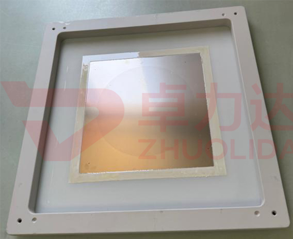
A BGA ball mount stencil is a precision electroformed metal template used to position and deposit solder balls onto the ball pads of a Ball Grid Array package during board-level and package-level ball mounting. Built by additive nickel-cobalt electroforming rather than etching or laser cutting, it produces near-vertical, smooth apertures that align with the dense ball array on the substrate. As BGA packages move toward finer pitch, higher I/O counts, and smaller ball diameters, the stencil directly determines ball placement accuracy, bridging rate, and mounting yield. The process supports pure nickel and nickel-cobalt alloys across thicknesses from 60 µm to 200 µm, with aperture tolerance in the single-digit micrometer range.
Parameter Window
• Available Materials: Pure nickel, nickel-cobalt alloy
• Material Thickness Range: 0.06–0.20 mm
• Aperture Tolerance: ±1–2 µm
• Minimum Feature: ≈ 1.0–1.2 × material thickness
• Surface / Hole-Wall Quality: Hole-wall Ra ≤ 0.6 µm, vertical sidewalls
• Tension: 38–45 N/cm, stable over production runs
Manufacturing Process / Workflow (8 Steps)
1. DFM & Artwork Review — Translate BGA ball pad layout into aperture compensation drawings, accounting for ball pitch, diameter, and array geometry.
2. Surface Pre-treatment — Degrease, acid-clean, and activate the mandrel substrate for uniform deposition.
3. Dry Film Lamination & LDI Exposure — Laminate photoresist and transfer the ball-array pattern by laser direct imaging.
4. Development — Reveal the precision aperture windows matching each ball pad.
5. Pulse Electroforming Deposition (Core Step) — Grow nickel-cobalt layer by controlled pulsed current, building vertical, low-stress sidewalls.
6. Stress Relief & Demolding — Anneal to release residual stress, then separate the free-standing stencil from the mandrel.
7. Tension Setting & Frame Mounting — Mount onto a frame and tension to specification.
8. Cleaning & Aperture Inspection — Class-100 clean wash followed by microscopy and dimensional inspection.
Core Advantages
1. Near-Vertical, Smooth Apertures — Electroformed holes have minimal taper and low roughness, so solder balls seat cleanly without bridging or misalignment.
2. Fine-Pitch Ball Reproducibility — Aperture pitch and diameter hold at micron scale, supporting shrinking ball pitch and smaller ball diameters.
3. Low Residual Stress — Pulsed deposition plus annealing yields a flat, dimensionally stable stencil that resists warping under tension.
4. Wear and Release Performance — Nickel-cobalt alloy is hard and durable; optional nano-coating reduces flux and paste adhesion and extends stencil life.
5. No Mechanical or Thermal Damage — Additive electroforming avoids burrs, heat-affected zones, and micro-cracks from stamping or laser cutting.
6. Design Flexibility — Pattern changes are made in artwork, not hard tooling, supporting rapid iteration for new BGA and CSP designs.
Typical Applications
• BGA Packages — Solder ball mounting on memory, logic, and ASIC substrates.
• CSP / WLCSP — Fine-pitch ball placement for chip-scale packages.
• FCBGA — High-I/O flip-chip ball grid array ball mounting.
• PBGA / CBGA — Plastic and ceramic BGA reballing and original ball attach.
• Module and SiP — Ball array for system-in-package modules.
• Repair and Reballing — Rework stencils for failed or aged BGA units.
Design Notes & Process Considerations
1. Compensate artwork for ball pad pitch and flux rheology so apertures align exactly with pads.
2. Balance stencil thickness against ball diameter—too thin risks deformation, too thick impedes ball release.
3. Specify nickel-cobalt alloy for high-cycle production; use pure nickel for prototyping.
4. Keep tension uniform across the frame to avoid positional drift of outer apertures.
5. Validate aperture cleanliness and partial blocking before each production run.
6. Pair with matched flux viscosity and ball feed for stable placement across the full array.
Contact:赖先生
Phone:+86 18938693450
Tel:0755-2708-8292
Email:yw9@zldsmt.com
Add:深圳市宝安区福永镇新和村福园一路华发工业园A3栋
 Zhuolida