Welcome: Shenzhen Zhuolida Electronics Co.TD
Language:
 ∷

∷
∷
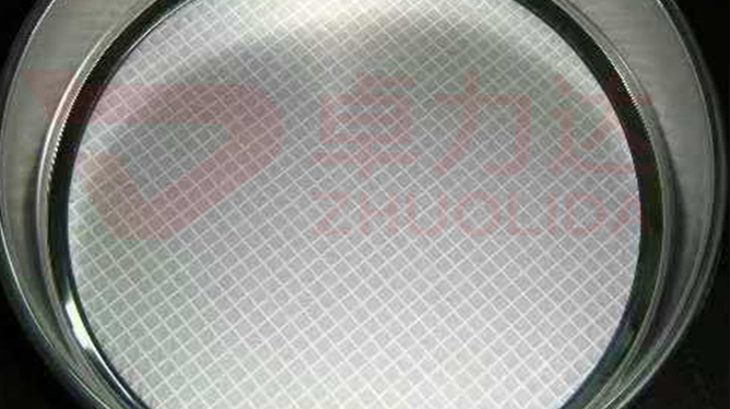
Electroformed microhole mesh flow uniformity verification governs whether flow capacity is even from one part of the sheet to another, not whether a single hole passes. A microhole mesh carries hundreds of thousands to millions of holes, and ± 3 μm aperture tolerance is measured hole by hole; yet let one zone develop off, carry a tapered wall, or stretch locally during framing and that patch of pressure drop drifts away from the rest. The line divides the face into 3 × 3 or 5 × 5 zones, measures flow zone by zone at a fixed pressure drop and converts it back to pressure drop, looking for skew in the whole-sheet distribution. Put plainly, dimensional inspection answers whether the holes are right, and flow uniformity verification answers whether this sheet can serve as a uniform flow field — the two need a report each.
The most common rework is vision-sampled apertures all sitting inside ± 3 μm while installed output runs heavy on one side and light on the other; zone the pressure drop and a corner patch comes in a notch under the centre — the edge resist ran slightly thinner at lamination, so development undercut quietly opened that zone of holes wider. On another lot of atomiser meshes, tensioning to 55 N thinned the centre zone, the array opened a little along the load direction, and the spray cone leaned to one side. Then there is local sticking at release, tens of thousands of aperture mouths left with an extremely thin ring of flash; single-hole dimensions did not budge, yet pressure drop lifted across the board. All of these slip past opening spot checks and surface only when flow or spray shape is accepted, by which time a batch is usually already filmed and blanked. Pull up a pressure-drop map and which zone the fault sits in, and roughly which step brought it, line up almost at once — far less work than rechecking every hole.
Parameter Window
• Aperture tolerance ± 3 μm and roundness ± 0.002 mm, sampled and rechecked zone by zone
• Zoned pressure drop: a 3 × 3 or 5 × 5 grid, each zone within ≤ ± 5% of the mean
• Pitch ≥ 120 μm, web ≥ 50 μm, minimum aperture ≥ 25 μm
• Stencil thickness 15–200 μm; uneven thickness rewrites local pressure drop directly
• Tension 10–55 N (± 1 N internal control), rechecked after framing so the centre zone is not thinned
• Test pressure drop fixed to the application band, no band changes within a lot so data stay comparable
Manufacturing Process (8 Steps)
1. Data zoning — divide the face into 3 × 3 or 5 × 5 by sheet size, write the zone numbers into the inspection card.
2. Lamination and LDI — 8 μm/8 μm resolution and ± 5 μm double-side alignment, the array shaped consistently across the sheet.
3. Development — control concentration and spray uniformity, no edge undercut, apertures hold ± 3 μm in every zone.
4. Electroforming — staged current at 1–4 A/dm², thickness even across the sheet, no local thickness drift accumulating.
5. Demolding — one-piece low-stress release, no sticking flash left at aperture mouths.
6. Inspection — vision and flash systems read aperture and roundness, checker scans the whole sheet of openings.
7. Zoned pressure-drop recheck — measure flow zone by zone at fixed pressure drop, convert to pressure drop, draw the whole-sheet map.
8. Framing and packing — AB adhesive frame fixed in 10–55 N bands, one more sample round after framing.
Core Advantages
1. Even across the sheet — electroformed microhole mesh flow uniformity verification holds zone pressure difference within ± 5%, so the flow field does not skew.
2. Caught early — local drift from development, release and framing shows up before shipping.
3. Two reports, dimension and performance — ± 3 μm apertures to the checker, pressure-drop map to the flow bench, each judged on its own.
4. Predictable throughput — screening, atomising and dispensing flow figured over the whole sheet, not extrapolated from one hole.
5. Faults localise — whichever zone drifts traces back to the development spray or framing load band.
6. Traceable — zone data, pressure-drop band and tension band archived per sheet, back to the specific bath run.
Typical Applications
1. Precision screens for semiconductor material grading, where uneven flow rewrites the screened particle-size distribution directly.
2. Microhole meshes for atomising and dispensing, where zone pressure drop sets spray cone angle and liquid uniformity.
3. Flow-field distribution plates for batteries and fuel cells, where whole-sheet resistance has to be flat.
4. Filter-membrane support meshes, where the end with higher local pressure drop clogs and fatigues first.
5. Porous attenuators for optics and inspection, where transmittance must match zone to zone.
6. Large-format photovoltaic grids, where uneven development and tension along the long edge drift pressure drop at both ends first.
Design and Selection Notes
1. Do not zone too coarsely; 3 × 3 is the floor, and a large sheet is better on 5 × 5 to expose edge drift.
2. Fix the test pressure drop to the application band; switching bands within a lot makes the data worthless to compare.
3. Verify development spray uniformity each lot; edge undercut is the most common root of low pressure drop.
4. Keep thickness even across the sheet; a few microns of drift inside 15–200 μm is enough to change local flow resistance.
5. Always measure one more round after framing; 55 N thinning the centre does not show up beforehand.
6. Check aperture-mouth flash at release; a thin ring from sticking leaves single-hole dimensions untouched and lifts pressure drop everywhere.
7. Give pressure-drop recheck its own flow bench; a flat-bed checker cannot read throughput distribution.
Laid out, electroformed microhole mesh flow uniformity verification fills exactly the stretch dimensional inspection cannot reach: ± 3 μm aperture tolerance guarantees each hole, but development undercut, release flash, framing stretch and thickness drift all quietly rewrite flow resistance at whole-sheet scale while the single-hole report reads pass every time. Zoned pressure-drop recheck cuts the face into a grid, and one distribution map lays out which zone drifted and by how much. If any zone in a lot falls more than 5% below the mean, hold release rather than rush it and go back through the development spray and framing records — eight times out of ten the root is there. What is hard on the line is not turning out a sheet with pretty apertures, but holding every zone steady at ± 5% across several consecutive lots and several pressure-drop bands, so the customer dares design against a uniform flow field. For orders with a hard flow-distribution requirement, fix the zoning scheme, test pressure drop, development spray parameters and framing tension band into the process card at sampling stage and run to that card in production; it is far cheaper than endlessly retuning conditions on the atomising bench and screening line. On paper electroformed microhole mesh flow uniformity verification is a set of pressure-drop numbers; on the line it is the fact that the whole sheet, centre to four corners, flows exactly the same.
Contact:赖先生
Phone:+86 18938693450
Tel:0755-2708-8292
Email:yw9@zldsmt.com
Add:深圳市宝安区福永镇新和村福园一路华发工业园A3栋
 Zhuolida