Welcome: Shenzhen Zhuolida Electronics Co.TD
Language:
 ∷

∷
∷
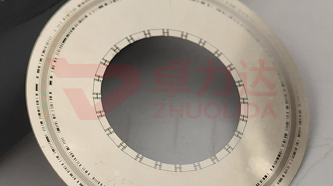
Stack two probe alignment templates into a fixture and each one can pass a ±7 μm position check on a vision system, yet a probe still will not go through. The fault is rarely in either sheet on its own; it sits in the alignment between the two faces. Probe alignment template multilayer alignment control governs one shared datum for the upper and lower guide holes: ±5 μm double-side alignment at LDI is only the starting line, because lamination, development, demolding and stacking each add a little error, most visibly at the corners of a 610×660 mm panel. None of it appears on a single-sheet ±3 μm aperture report, yet it decides whether a probe runs all the way through after stacking. It comes down to three things: an accurate datum code track, matched double-side exposure, and one more measurement of accumulated error after the stack is made.
This kind of rework eats the most time on the floor because every single sheet passes full inspection. A batch of two-layer templates goes on the machine stacked and bends probes in a band across the middle; pulled apart, each sheet still measures inside ±7 μm, and only re-stacking the two on a flash measurement shows the upper and lower holes offset sideways by 8 μm, right against the probe diameter. Reverse the lamination direction and the resist shrinks slightly after development: the double-side marks still read true, but the stack ends up offset to either side of the centre line and the 50 μm ±0.5 μm code track reading jumps with it. More subtle still: expose a full 610×660 mm panel in one pass to clear a large-format backlog and ±5 μm holds at the centre, while substrate expansion pulls the four corners a few microns apart and corner probes butt against the mouth first. None of these faults fall inside the single-sheet judgement of an automatic stencil checker, and by the time they surface the two layers are usually already spot-welded into an assembly. Probe alignment template multilayer alignment control is harder to land than single-sheet inspection precisely because the error is built up by stacking, which no single-sheet measurement can see.
Parameter Window
• Double-side alignment ±5 μm and LDI resolution 8 μm/8 μm, alignment marks exposed in the same pass as the guide holes
• Single-sheet position accuracy ±7 μm and aperture accuracy ±3 μm, accumulated error judged separately after stacking
• A 50 μm ±0.5 μm code track as the alignment datum, with the line stopped for re-check if the reading drifts
• Ball-template total pitch ±7 μm, sampled across the full panel after stacking rather than at the centre only
• Maximum substrate 610×660 mm, corner-to-centre alignment difference logged alongside every stack
• Tension 10–55 N banded, the same band before and after stacking so the frame does not pull the stack off
Manufacturing Process (8 Steps)
1. Artwork preparation — one shared datum code track for both layers, guide holes and alignment marks on the same master.
2. Pre-treatment — substrate cleaning and conductive coating, expansion controlled, large panels located at all four corners.
3. Lamination and LDI — double-side imported LDI exposure at 8 μm/8 μm resolution and ±5 μm alignment, front and back aligned in one pass.
4. Development — concentration and temperature held so both resist layers move together and the alignment marks do not drift.
5. Electroforming — staged current density at 1–4 A/dm², both layers in the same bath conditions to cut thickness mismatch.
6. Demolding — one-piece release from a low-stress corner, keeping the mark zone undistorted.
7. Inspection — checker for single-sheet openings, vision and flash measurement reading the code track and hole positions.
8. Stack re-measurement — layers mated by the marks, accumulated error and corner difference re-checked, then spot-welded or fixed with AB adhesive.
Core Advantages
1. Stacks that mate — put probe alignment template multilayer alignment control into a shared datum and post-stack re-measurement, and probes stop bending in bands.
2. Steady on large panels — centre and four corners watched together on 610×660 mm, so corner alignment does not drop first.
3. Error broken out — single-sheet ±7 μm and stack accumulation logged apart, so a fault is pinned to exposure or to mating.
4. Datum as a guard — a 50 μm ±0.5 μm reading that jumps stops the line before the fault reaches welding.
5. Fewer teardowns — a re-check before mating replaces rework after welding, so neither layer is wasted.
6. Traceable — double-side exposure dose, substrate lot and stack re-measurement go on the process card and reach back to a shift.
Typical Applications
1. Two-layer wafer probe card guide assemblies, where a small upper-to-lower offset bends probes.
2. Stacked alignment of 4–12 inch WLP ball-placement templates, where total pitch ±7 μm must hold across layers.
3. Multilayer guides in ABF substrate test fixtures, which still have to pass probe through-travel after stacking.
4. Encoder stacks with a 50 μm ±0.5 μm code track, where alignment drift pulls the reading off directly.
5. Two-layer apertures with 20 μm diaphragm ribs, where a layer mismatch leaks light.
6. 610×660 mm large-format grid stacks, where corner expansion tests alignment hardest.
Design and Selection Notes
1. In probe alignment template multilayer alignment control start from a shared datum code track; never let the two layers keep separate origins.
2. Align both sides in one exposure pass; splitting the face slowly eats away the ±5 μm.
3. Lock development temperature per lot; let the resist stretch and shrink and the marks travel with it.
4. Do not measure only the centre on large panels; corner-to-centre differences on 610×660 mm belong in the re-measurement sheet.
5. Give stack accumulated error its own station, since a single-sheet checker cannot judge offset between two layers.
6. Set tension within one 10–55 N band and keep the same band across stacking, or the frame will pull the stack off.
7. Leave one re-measurement before welding or AB-adhesive fixing; pulling a finished stack apart costs far more.
Seen on its own, probe alignment template multilayer alignment control barely occupies a standalone step: the datum code track is fixed at artwork, ±5 μm double-side alignment is matched at LDI, resist movement is buried in development, substrate expansion adds a little at the panel corners, and the act of stacking finally spreads all of it out. Pre-treatment, exposure, development and mating each own a stretch of it, and let any one slip and the ±5 μm will not hold. What is hard on a line is not turning out one assembly that takes probes smoothly now and then, but keeping a dozen assemblies from one lot and several consecutive shifts inside the same band of centre-to-corner difference, code track reading and stack accumulation — only then does a single-sheet ±7 μm position mean anything. For two-layer or large-panel orders, fix the datum code track, double-side exposure dose, development temperature and stack re-measurement sheet into the process card at sampling stage and run to that card in production; it is far cheaper than picking assemblies one by one on a flash measurement after welding and pulling them apart. On paper probe alignment template multilayer alignment control is a string of parameters; on the line it is the simple fact that two layers of holes line up across the whole panel.
Contact:赖先生
Phone:+86 18938693450
Tel:0755-2708-8292
Email:yw9@zldsmt.com
Add:深圳市宝安区福永镇新和村福园一路华发工业园A3栋
 Zhuolida