Welcome: Shenzhen Zhuolida Electronics Co.TD
Language:
 ∷

∷
∷
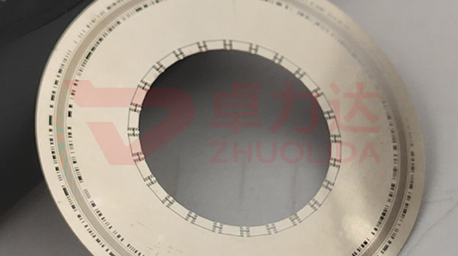
A probe alignment template can pass ±7 μm position and ±3 μm aperture checks before shipping, then run a few heating and cooling rounds inside the tool, come off and measure a few microns off in one consistent direction, and take probes badly. Probe alignment template thermal cycling stability verification governs whether dimensions still hold after that cycling: the nickel layer, the AB-adhesive frame and the substrate each expand on their own terms, stress left in the deposit releases slowly, and once tension slackens the hole positions follow. None of it appears on the outgoing ±3 μm aperture report, yet it decides how long the template lasts in real service. It comes down to three things: let a low-temperature anneal release deposition stress first, leave margin in the framing tension, and re-measure drift before and after cycling.
On the floor this is most often written off as a mounting error. A batch sweeps clean at ±7 μm on a flash measurement at room temperature, then probes start striking off-centre after continuous furnace runs; stop and re-measure and the centre is fine while the four corners have spread outward by 6 μm, exactly the expansion mismatch between nickel and frame accumulated. Skip the low-temperature anneal on the next lot to save time and the same plate drifts on the first heating round and does not come all the way back on cooling, so the residual stacks up round after round. More subtle still: frame the sheet tight at 55 N and it looks flat cold, but heat softens the adhesive first, tension drops and hole positions loosen with it — a vision system reads the dimensions and cannot tell that tension was lost. None of these faults fall inside the room-temperature judgement of an automatic stencil checker, and by the time they surface several furnace loads have usually been scrapped. Probe alignment template thermal cycling stability verification is harder to land than outgoing inspection precisely because the drift only shows itself after temperature cycling.
Parameter Window
• Room-temperature position accuracy ±7 μm and aperture accuracy ±3 μm, taken as the pre-cycling baseline
• Post-cycling hole position drift held inside ±7 μm, centre and four corners logged as separate differences
• Low-temperature anneal to relieve stress, with position measured on both sides of the anneal
• Tension 10–55 N (held to ±1 N internally), never mixed within a lot so heat does not drop tension
• Nickel-cobalt hardness 450–550 Hv, hardness band and anneal curve logged together
• Maximum substrate 610×660 mm, corner drift judged on its own rather than as a whole-panel average
Manufacturing Process (8 Steps)
1. Artwork preparation — master data for the probe array, with re-measurement datum holes and corner marks flagged.
2. Pre-treatment — substrate cleaning and conductive coating, low-adhesion mandrel passivation, deposition stress controlled.
3. Lamination and LDI — imported LDI exposure at 8 μm/8 μm resolution and ±5 μm double-side alignment; datum marks formed in the same pass.
4. Development — control concentration and time so no residue stays at the foot and datum marks stay sharp enough to re-measure.
5. Electroforming — nickel-cobalt staged current density at 1–4 A/dm² to cut deposition stress.
6. Demolding — one-piece release from a low-stress corner, keeping the mark zone undistorted.
7. Inspection and anneal — checker for openings, vision and flash measurement for the room-temperature baseline, then a low-temperature anneal and a position re-check.
8. Framing and cycle re-measurement — fixed into an AB-adhesive frame at 10–55 N, temperature-cycled to the customer's working range, and re-measured before and after.
Core Advantages
1. Drift predicted — build probe alignment template thermal cycling stability verification into the re-measurement sheet and you know whether hole positions will move after mounting.
2. No stacking residual — the low-temperature anneal releases stress, so positions do not wander further after several rounds.
3. Tension holds — margin left in the 10–55 N band keeps hole positions from loosening even when heat softens the adhesive.
4. Corners judged too — four corners measured separately on 610×660 mm instead of being smoothed away by a centre average.
5. Traceable faults — anneal curve, tension band and before/after re-measurements go on the process card and reach back to a bath run.
6. Fewer scrapped loads — cycle verification before shipping avoids trial-and-error with whole furnace loads on the tester.
Typical Applications
1. Wafer probe card guide plates, where tool heating and cooling is everyday service.
2. Alignment holes of 4–12 inch WLP ball-placement templates, where total pitch ±7 μm must hold through heat.
3. Probe guides in ABF substrate test fixtures, where continuous furnace runs bring clear temperature swings.
4. Encoder templates with a 50 μm ±0.5 μm code track, where a drifting hole makes the reading jump.
5. 610×660 mm large-format grid stacks, where corner expansion shows most clearly.
6. Composite templates with post height or local thickening, where stress release concentrates at the step root.
Design and Selection Notes
1. In probe alignment template thermal cycling stability verification fix the re-measurement baseline first; without a clean room-temperature ±7 μm record there is nothing to compare against after cycling.
2. Never skip the low-temperature anneal; deposition stress that releases only after mounting is the worst kind.
3. Band tension within 10–55 N and leave margin rather than pulling to the ceiling; heat drops that setting first.
4. Set the cycling range from the customer's actual tool, and do not treat a room-temperature report as the conclusion.
5. Measure corners and centre apart, since a whole-panel average flattens corner drift away.
6. Re-measure on the same vision system with the same datum holes; change either and the data stops comparing.
7. Where local thickening exists, check the step root for micro-cracks on both sides of the anneal.
Seen on its own, probe alignment template thermal cycling stability verification barely occupies a standalone step: deposition stress is buried in the bath, the low-temperature anneal decides how much of it leaves, the AB-adhesive frame and tension decide what slackens first under heat, and the rounds of cycling finally bring all the stored residual out at once. Pre-treatment, exposure, deposition, annealing and framing each own a stretch of it, and let any one slip and the ±7 μm post-cycling position will not hold. What is hard on a line is not turning out one room-temperature-good plate now and then, but keeping a dozen plates from one bath and several consecutive lots inside the same band of before/after difference, corner drift and post-anneal baseline — only then does ±3 μm aperture accuracy mean anything. For orders meant to run furnace rounds for the long haul, fix the anneal curve, tension band, datum holes and cycling range into the process card at sampling stage and run to that card in production; it is far cheaper than recalibrating probes on the tester and burning whole furnace loads to find out. On paper probe alignment template thermal cycling stability verification is a string of parameters; on the line it is the simple fact that hole positions are still where they were after the heat comes and goes.
Contact:赖先生
Phone:+86 18938693450
Tel:0755-2708-8292
Email:yw9@zldsmt.com
Add:深圳市宝安区福永镇新和村福园一路华发工业园A3栋
 Zhuolida