Welcome: Shenzhen Zhuolida Electronics Co.TD
Language:
 ∷

∷
∷
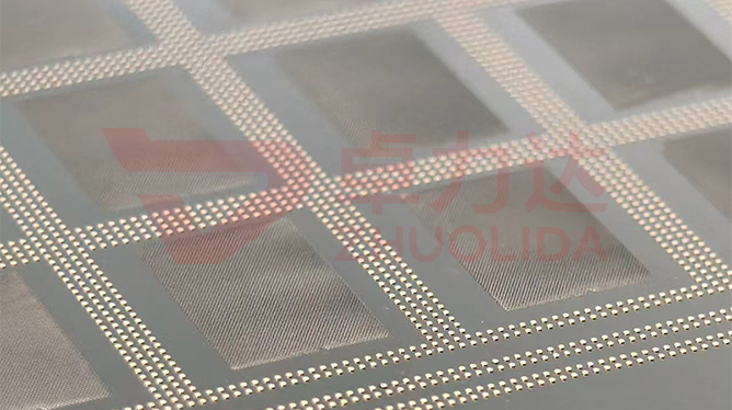
An electroformed aperture blade is only tens of microns thick, with ribs just 20μm wide; a multi-stage aperture stacks three to five such leaves along the optical axis, cutting the clear aperture from openings that shift against each other. The axial slit between blades is the stack gap. It never appears on a single-blade drawing, yet it decides whether stray light leaks into the field through the slit and whether blades scrape each other as they rotate. Electroformed aperture blade stack gap control governs that slit: press it to a few microns and the light-blocking boundary stays sharp; leave it too wide and light leaks, too tight and the stack binds, so thickness tolerance and flatness have to be computed together with the gap. Aperture roundness and clear aperture are already calibrated; the hard part is making the blades fit so no stray light passes between them.
Multi-stage apertures that come back from the field seldom fail at a single opening; the trouble sits in those few microns of stack. One five-blade lens-barrel aperture measured every clear aperture inside tolerance, but pointed at a point source the outer field carried a grey halo. Teardown showed the third blade 4μm thicker than its batch mates, tilting the whole stack into a wedge slit that let stray light through; wiping and swapping blades did not fix it. Another lot went the other way: assembly squeezed the gap too tight, the blades grew gritty after two or three turns and the coating was scored bright by the neighbour, jamming the return stroke within days. Subtler still, an incomplete low-temperature anneal let internal stress release slowly after mounting, flatness drifted a few microns, and a clean light-blocking boundary began leaking again a week later. Single-blade inspection passes all of this: an imager measures aperture outlines and position accuracy ±7μm, it cannot read the real gap of an assembled stack, and by the time it shows up the whole barrel lot needs rework. Electroformed aperture blade stack gap control has to treat the gap as its own fit quantity, not release it mixed into single-blade dimensions.
Parameter Window
• Blade thickness 15–50μm in classes, within-stack spread ≤3μm, rib line width 20μm
• Light-blocking boundary checked against the stack gap given by the assembly side, commonly 3–8μm; single blades hold only thickness and flatness
• LDI resolution 8μm/8μm, double-side alignment ±5μm, blade openings and ribs aligned in one shot
• Position accuracy ±7μm, aperture tolerance ±3μm, roundness ±0.002mm remeasured at a separate station
• Current density 1–4A/dm² in stages, nickel-cobalt alloy hardness 450–550Hv, RoHS compliant
• Maximum substrate 610×660mm; blades of one stack taken from the same sheet so the spread stays small
Manufacturing Process (8 Steps)
1. Data and drawing — lay out blade openings and ribs from the clear aperture, set thickness class and within-stack spread.
2. Pretreatment — clean and conductivize the base so plating starts evenly and thin blades show no pinholes or warp.
3. Lamination and LDI — 8μm/8μm resolution, double-side alignment ±5μm, the 20μm ribs imaged in one pass.
4. Developing — hold concentration and time, leave no residue or undercut at the rib edge so the light-blocking boundary stays sharp.
5. Electroforming — current density 1–4A/dm² in stages, stop at the class, sample spread per bath.
6. Release and anneal — peel the whole sheet from a low-stress corner, low-temperature anneal to relax stress and hold flatness.
7. Inspection — checker scans openings, imager and flash gauge measure position and roundness, thickness logged per blade.
8. Class packing — sort by measured thickness, mark spread and flatness; whether stacking is done in this plant follows the order agreement.
Core Advantages
1. Clean light-blocking boundary — hold electroformed aperture blade stack gap control and no stray light passes between blades, no grey halo in the field.
2. Smooth rotation — with travel margin in the gap, blades do not score each other as they shift.
3. Consistent stack — blades from one sheet keep the spread within ≤3μm, so the stack does not tilt into a wedge slit.
4. Size and fit managed apart — openings go to the checker, the gap to the process card, anomalies trace back to a thickness class.
5. Stable over time — low-temperature anneal relaxes internal stress so flatness does not creep after mounting.
6. Traceable — each blade logs thickness, flatness and position, so a bad match traces back to a bath run.
Typical Applications
1. Multi-stage apertures in microscope and camera barrels, where three to five blades depend most on light-blocking fit.
2. Baffle blade sets ahead of a spectrometer entrance slit, where a little stray light lifts the baseline.
3. Energy apertures on laser processing heads, where blade gap decides how steep the edge cutoff is.
4. Field apertures on semiconductor inspection tools, built from stacked 20μm-rib thin blades.
5. Variable apertures in medical endoscope illumination paths, where more blades demand a more consistent gap.
6. Stacked precision sieves and micro-hole mesh classification parts, whose hole alignment also rests on low thickness spread.
Design and Selection Notes
1. Set the opening from the clear aperture first, then back out blade thickness class and stack gap; do not release on single-blade pass alone.
2. Confirm whether multi-stage stacking is done in this plant; this article covers only the gap window that single-blade precision can support.
3. Take blades of one stack from the same 610×660mm sheet; spread matters more than the absolute thickness.
4. Do not rush developing on a 20μm rib edge; a few tenths of a micron of undercut blurs the light-blocking boundary.
5. Do not skip the low-temperature anneal; stress left in place drifts flatness and leaks light within days of mounting.
6. Sample the blade thickness profile per bath for electroformed aperture blade stack gap control; total thickness alone hides the spread.
7. Use an imager and flash gauge for position and roundness, and a separate station for stack gap remeasurement; a checker cannot scan the slit.
Break electroformed aperture blade stack gap control apart and no single step owns it: LDI and developing fix the openings and ribs, the bath decides which thickness class to stop at, and release plus anneal decide whether a blade warps slowly after mounting. Pretreatment, exposure, deposition and peeling each guard one stretch, and if any loosens the slit between blades will not hold. Thickness spread follows current density and deposit time, so it has to be sampled per bath instead of judged from a single-blade total. What is hard is not one stack that happens to block light, but a dozen blades from the same bath and several consecutive lots all sitting in the same thickness and flatness class. Only then does ±7μm position accuracy mean anything. For multi-stage orders with many blades, fix the thickness class, the spread ceiling and the anneal conditions in the process card at the sampling stage and run production to that card; it is far cheaper than shimming and swapping blades at the assembly end. Whether stacking is done in this plant follows the order agreement, so recheck the light-blocking boundary on a matched sample before it goes on the drawing.
Contact:赖先生
Phone:+86 18938693450
Tel:0755-2708-8292
Email:yw9@zldsmt.com
Add:深圳市宝安区福永镇新和村福园一路华发工业园A3栋
 Zhuolida
