Welcome: Shenzhen Zhuolida Electronics Co.TD
Language:
 ∷

∷
∷
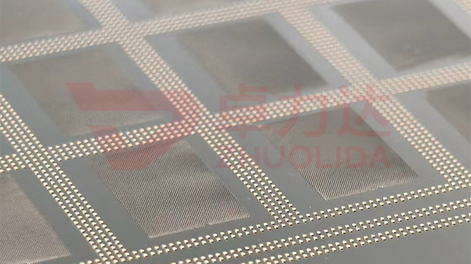
This plate is not a micro-hole sieve mesh. A probe positioning template mounts on a probe card and its guide holes set where the needle tips land, so the absolute coordinate of each hole relative to the datum hole is the functional quantity; a micro-hole mesh is judged by whether adjacent-hole pitch is even and aperture tolerance ±3μm passes. Probe positioning template cumulative hole position deviation control governs something else: from the first hole of the array to the last, whether deviation piles up across the full span and pushes the last hole out of window. Per-hole position accuracy ±7μm is a single-hole figure and a passing pitch is only a local one; over several thousand holes, LDI zone stepping, substrate stress and developing plus electroforming distortion each add a little systematic drift, and the last hole can wander tens of microns. Acceptance does not measure pitch hole by hole; it measures the absolute deviation of first and last holes against the datum in one setup.
On the floor a drifting last hole is usually blamed on assembly or the probe card. One lot of probe positioning templates rechecked inside ±7μm on every hole with pitch even, yet on the prober the last row of tips missed the pads; a full-field imager measurement showed the first hole true and the last out by over 30μm along X, from one or two microns of stepping error carried into each LDI exposure zone. Another lot measured fine sheet by sheet, but after annealing the whole plate bowed slightly and the center-to-edge holes were pulled into a diagonal line, last-hole deviation growing linearly with span. More wearing still: substrate moisture uptake after developing and electroforming stress release each add a bit, so one lot drifts left and the next right, and sampling a few middle holes shows nothing. Probe positioning template cumulative hole position deviation control is hard because the automatic checker judges holes one by one and reports single-hole coordinates, never the convergence curve between first and last; by the time the probes land off, a whole wafer of test points has been cycled.
Parameter Window
• Per-hole position accuracy ±7μm and aperture accuracy ±3μm; cumulative deviation computed separately from first and last hole absolute coordinates
• First-to-last convergence target ≤±10μm over a 610×660mm full field, classed by array span
• Minimum aperture ≥25μm, pitch ≥120μm, web ≥50μm; the more holes, the closer accumulation is watched
• LDI resolution 8μm/8μm, double-side alignment ±5μm; zone stitching step error logged per zone
• Wall roughness ≤0.01μm and nickel-cobalt hardness 450–550Hv; distortion and tip wear managed together
• Current density 1–4A/dm² with low-temperature anneal; whole-sheet flatness enters the accumulation budget
Manufacturing Process (8 Steps)
1. Data and drawing — set the datum hole and locating edge from the probe array map, write first and last hole coordinates as the acceptance basis.
2. Pretreatment — clean and conductivize the base, passivate the mandrel face so plating starts evenly and later stress stays uniform.
3. Lamination and LDI — 8μm/8μm resolution, double-side alignment ±5μm, calibrate zone stitching step zone by zone.
4. Developing — control concentration, time and substrate temperature and humidity, leave no residue at the bottom, avoid moisture-driven distortion shifting holes.
5. Electroforming — current density 1–4A/dm² in staged control, stop the moment target thickness is reached.
6. Demolding — peel the electroformed part off the mandrel from a low-stress corner so apertures do not collapse and coordinates hold.
7. Low-temperature anneal — relieve nickel-cobalt internal stress and flatten, erasing the center-to-edge drift line.
8. Full-field inspection — an imager and a flash gauge measure first and last holes and four corners in one setup, then issue the convergence curve and frame.
Core Advantages
1. Last hole holds — bringing probe positioning template cumulative hole position deviation control into one convergence class stops first and last holes from drifting apart.
2. One setup judges the full field — not inferred from per-hole passes, but read as absolute deviation of first and last holes against the datum.
3. Stitching error traceable — LDI zone steps are logged per zone, so the direction of accumulation tracks back to a specific exposure zone.
4. Size and position split apart — ±3μm aperture accuracy goes to the checker, accumulation to the process card, anomalies down to a bath run.
5. The stress line flattened — demolding paired with low-temperature anneal presses the center-to-edge linear drift down.
6. Traceable — every sheet keeps measured first and last holes, flatness, anneal lot and stitching log, traceable to a bath run.
Typical Applications
1. Probe card guide plates on wafer probers, where thousands of needles land true only if first and last holes converge.
2. High-frequency test probe card positioning templates, where wide array span makes last-hole deviation most sensitive.
3. Datum hole plates for multi-layer alignment fixtures, where inter-layer datums rely on full-field coordinates not drifting.
4. MEMS wafer-level test positioning plates, where accumulation shows up more at pitch ≥120μm.
5. Burn-in probe array boards, with many holes and long spans, needing their own convergence class.
6. Large-format panel probe fixtures, first and last holes measured across a 610×660mm field in one setup.
Design and Selection Notes
1. Separate the objects first. Probe positioning template cumulative hole position deviation control governs first and last hole absolute coordinates, not the pitch and ±3μm aperture tolerance of a micro-hole mesh.
2. Do not treat per-hole passes as convergence — every ±7μm hole can pass while the last still drifts tens of microns over several thousand holes.
3. Write the measurement basis into the drawing: imager and flash gauge in one setup, report absolute deviation of first and last holes against the datum, not mean pitch.
4. Calibrate stepping zone by zone — one or two microns of LDI stitching error per zone becomes a systematic offset at the last hole.
5. Manage substrate and anneal together — temperature and moisture distortion plus electroforming stress pull center to edge into a diagonal line.
6. Double-side alignment ±5μm is the floor; once front and back offset, first-to-last convergence is out of the question.
7. Sample first and last holes and four corners, not just the middle; passing middle holes cannot reveal drift accumulated along the span.
Break probe positioning template cumulative hole position deviation control apart and it owns no single step: the datum and first and last hole coordinates are fixed in data prep and LDI, zone stitching feeds in systematic error inch by inch, and developing, electroforming, demolding and annealing each add a little distortion — every stretch that accumulates a bit nudges the last hole out a bit. Cumulative deviation follows exposure zones, substrate lot and anneal curve, so convergence curves have to be sampled per bath in one full-field setup. What is hard is not measuring one sheet with first and last aligned by chance, but keeping a dozen sheets from the same bath and several consecutive lots drifting in the same direction and class — only then does ±7μm per-hole position accuracy mean anything, and probes landing true stops being luck. For orders with a hard requirement on probe card alignment, fix the datum hole definition, zone step compensation, anneal curve and full-field measurement basis in the process card at sampling and run production to that card; it is far cheaper than endlessly adjusting fixtures, shifting the card and re-aligning at the prober. This is a ledger kept in absolute coordinates; do not apply a micro-hole mesh's pitch ruler to it.
Contact:赖先生
Phone:+86 18938693450
Tel:0755-2708-8292
Email:yw9@zldsmt.com
Add:深圳市宝安区福永镇新和村福园一路华发工业园A3栋
 Zhuolida
