Welcome: Shenzhen Zhuolida Electronics Co.TD
Language:
 ∷

∷
∷
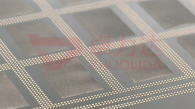
Several ring openings on one blade look like concentric circles, yet once mounted in a barrel they may not share the optical axis at all. Aperture blade concentricity control process governs the coaxial relation between those rings and of the whole set against the locating datum: whether the centre of each ring, separated by 20 μm fine ribs, has drifted, and whether front and back exposures line up. Concentricity is not about a single ring being round, but about many rings sharing one axis, judged on the line by scanning each ring centre with a vision system and comparing the locating holes to the opening centre with flash measurement. Measure the opening size as accurately as you like, and a few microns between rings still tips the light-passing centre off, with stray light and vignetting following it in.
The trap on the line is handing concentricity off as single-ring roundness. On one lot of double-side exposed blades the front rings all measured true, but the back had slipped five or six microns in master alignment and the mounted light-passing centre clearly sat to one side; the cause was LDI double-side alignment that was never locked. On a rushed lot the multi-ring pattern was stitched from two exposures, a fleck of resist propped up the datum hole during the second overlay, and the outer ring shifted as a whole, invisible on one blade but off-axis once stacked into the lens group. More hidden still, a fine rib was pulled slightly out of shape at demold; the ring was still there but its centre had moved, and only a ±0.002 mm roundness re-check caught it. None of these failures are written into the opening width, and by the time imaging finds them a whole batch of lenses usually needs re-matching. Aperture blade concentricity control process is hard to put into practice precisely because it governs the relative relation between rings and between faces, which scanning a single opening cannot reveal.
Parameter Window
• Fine rib width: 20 μm; band position drifts along with rib deformation
• Double-side alignment: ±5 μm, with the datum locked in one LDI lamination exposure
• Hole position accuracy: ±7 μm, locating holes and ring centres re-checked apart
• Roundness: ±0.002 mm; ring profile error amplifies into eccentricity
• Multi-ring coaxiality: centre deviation limits banded by ring count
• Substrate size: up to 610×660 mm, where large-panel tiling tests alignment hardest
Manufacturing Process (8 Steps)
1. Master design — put multi-ring pattern and locating datum on one master to avoid a second overlay shift.
2. Substrate pre-treatment — clean and make conductive, marking the datum separately at the locating-hole zone.
3. Lamination and LDI — ±5 μm double-side alignment at 8 μm/8 μm resolution locks front and back to one axis.
4. Development — control concentration and time so no residue stays at the rib foot and the sidewall is not undercut.
5. Electroforming — staged control of 1–4 A/dm² so fine ribs grow evenly without bulging at the rim.
6. Demolding — one-piece release from a low-stress corner; a 20 μm rib is most easily pulled crooked here.
7. Inspection — vision system scans each ring centre, flash measurement compares locating holes to the light-passing centre.
8. Matched release — supply lens groups banded by coaxiality, with a multi-ring centre re-check record attached.
Core Advantages
1. No off-axis drift — aperture blade concentricity control process locks rings and datum on one master, so the light-passing centre sits on the optical axis.
2. Front and back agree — one ±5 μm alignment pass keeps the two faces from fighting, with vignetting falling off sharply.
3. Ribs stay straight — development and demold both watch the 20 μm ribs, so ring centres are not pulled out of place.
4. Stable on large panels — within 610×660 mm tiling, every blade lands in the same coaxiality band.
5. Traceable — alignment value and each ring centre deviation are logged per master, so a fault reaches back to an exposure lot.
6. Easier assembly — supplying by coaxiality band cuts repeated centring work at the lens group.
Typical Applications
1. Fixed apertures in microscope and camera lenses, whose light-passing centre must sit on the optical axis.
2. Multi-ring vignetting apertures, where many rings accumulate eccentricity most fussy about coaxiality.
3. Mode-limiting apertures in laser paths, where a small offset clips the edge of the mode field.
4. Double-side aligned blades, whose front and back openings must share a single axis.
5. Large-panel tiled aperture sets, where blade-to-blade concentricity has to match.
6. Precision ring-band blades with 20 μm fine ribs, where rib deformation carries the ring centre with it.
Design and Selection Notes
1. Keep rings and datum on one master where possible. A second overlay is the biggest source of eccentricity.
2. Lock double-side alignment before exposure; do not expect downstream sorting to make up ±5 μm.
3. Give aperture blade concentricity control process its own station; scanning each ring centre is not the same as reading single-ring roundness.
4. Do not rush development. A few tenths of a micron of undercut at the rib foot moves the ring centre with it.
5. Choose a release direction that avoids dense rib zones; one crooked pull tips the whole ring set.
6. Measure locating holes and the light-passing centre apart; ±3 μm aperture accuracy cannot stand in for coaxiality.
7. Re-check every blade on a tiled panel; alignment drift at the border is the easiest to miss.
Seen on its own, aperture blade concentricity control process barely fills a standalone step: whether the rings share an axis is decided when the master puts them out together and LDI locks front to back, while development undercut, electroformed growth and rib pull at demold each own a stretch; let any one slip and the rings each drift a little. Coaxiality follows the alignment lot, bath temperature and tile position, so it has to be scanned per master and re-checked per blade rather than let one ring-centre sheet speak for a whole panel. What is hard on a line is not producing one well-centred blade now and then, but keeping a dozen blades from one master and several consecutive lots with the light-passing centre true once mounted in a barrel, only then do 20 μm ribs and ±5 μm alignment become a clean image. For multi-ring, double-side or large-panel orders, fix datum layout, alignment value, development time and release direction into the process card at sampling stage; running to that card beats repeated centring at the lens group and sorting by luck. On paper aperture blade concentricity control process is a few groups of centre deviations; on the line it is the plain fact that every blade mounts with the axis true and stray light held down.
Contact:赖先生
Phone:+86 18938693450
Tel:0755-2708-8292
Email:yw9@zldsmt.com
Add:深圳市宝安区福永镇新和村福园一路华发工业园A3栋
 Zhuolida
