Welcome: Shenzhen Zhuolida Electronics Co.TD
Language:
 ∷

∷
∷
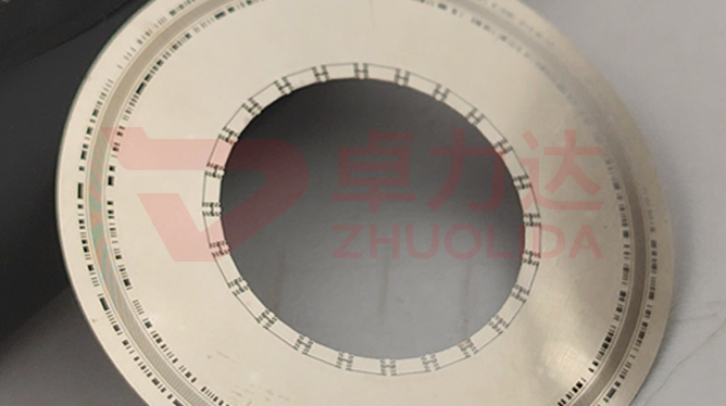
Mounted on a servo shaft, a disc can pass every static dimension and still start to shake as it climbs past ten thousand rpm, and the cause is more often mass distribution than the track itself. Electroformed encoder disc dynamic balancing process governs how evenly the nickel is laid across the whole face: if a 30–200 μm deposit runs thicker on one side, the centre of mass shifts off the rotation axis, and at speed that small offset is amplified into vibration and reading jitter. What it measures is not the total weight of one sheet but whether the mass in each annular band sits symmetric about the axis, judged on the line by an area thickness scan, residual unbalance and a trial-spin runout together. A 50 μm ± 0.5 μm track cut as accurately as you like still gives a wandering encoder output if the disc itself is off-centre.
The trap on the line is pushing balancing onto downstream weight removal. On one lot the fixture edge ran current-dense, so the outer ring grew three or four microns thicker than the centre; inspection checked only total thickness, saw it in tolerance and released the batch, then at rated speed a periodic shake appeared and a mass distribution re-check finally showed one side heavy. On a rushed lot a corner was lifted slightly at demold, flatness went unmeasured, that corner whipped first on the trial spin and the bearing soon grew noisy. More hidden still, a locally thickened disc had a sharp mass step where the build-up met the body; everything looked fine at low speed, yet a doubled-frequency vibration showed up the moment it spun fast. None of these failures appear in a 50 μm ± 0.5 μm track re-check, and by the time they surface a whole batch usually comes back for re-balancing. Electroformed encoder disc dynamic balancing process gets its own line because it spans deposition, demold and anneal, and no single station can level it with one scan.
Parameter Window
• Nickel thickness: 30–200 μm; in-sheet thickness spread held to ≤2 μm internally
• Track width: 50 μm ± 0.5 μm; eccentricity makes the reading drift with angle
• Roundness: ±0.002 mm; outer-profile error turns straight into mass eccentricity
• Bath current density: 1–4 A/dm², with a shielding ring at the fixture edge to even the flow
• Residual unbalance: upper limits banded by disc diameter, re-checked after a trial spin
• Low-temperature anneal: relieve deposition stress, then re-scan in-plane thickness
Manufacturing Process (8 Steps)
1. Mandrel and fixture design — lay out contacts by disc diameter, leave a shielding ring at the edge to even current.
2. Substrate pre-treatment — degrease and activate, then measure in-plane conductivity; uneven flow starts here.
3. Lamination and LDI — imported LDI at 8 μm/8 μm resolution shapes the track and annular bands.
4. Electroforming — staged control of 1–4 A/dm² and bath temperature, with periodic flipping to cancel one-sided build-up.
5. Demold and flatten — one-piece release from a low-stress corner, then measure flatness and lifted corners.
6. Mass distribution re-check — vision and flash measurement scan in-plane thickness and convert it to residual unbalance.
7. Dynamic balancing — local micro-removal or added mass in a reserved band, converging eccentricity by class.
8. Trial-spin release — run to rated speed on the shaft, with an anneal re-scan record attached.
Core Advantages
1. Steady at speed — electroformed encoder disc dynamic balancing process converges in-plane thickness up front, so doubled-frequency vibration drops off sharply.
2. Little removal — build-up is held back in deposition, so downstream correction is small and the track stays untouched.
3. Roundness kept — demold flattening and profile re-check work together, so ±0.002 mm is not left to luck.
4. Diameter changes are easy — 30–200 μm discs share one flow-evening and re-check logic.
5. Traceable — flip cadence, area thickness and trial-spin runout are logged per bath, so eccentricity reaches back to a run.
6. Truer bearing life — with the centre of mass on the axis, the shaft sees cleaner loading over long high-speed service.
Typical Applications
1. High-speed servo motor feedback discs, where rated speed is high and eccentricity cannot be ignored.
2. Absolute multi-track discs, whose many bands accumulate build-up and need per-band re-checks.
3. Large-diameter metal discs, where a one-micron thickness spread already scales into eccentricity.
4. Thin glass-substrate discs, low in stiffness, where a demold lift directly shifts mass distribution.
5. Composite discs with local thickening, whose build-up junction must be balanced on its own.
6. High-stability discs that need annealing, where an in-plane thickness re-scan after anneal is mandatory.
Design and Selection Notes
1. Set the flow-evening scheme by diameter first. Current crowds the edge, so a shielding ring beats removal after the fact.
2. Do not run deposition straight through. Flip midway and stage 1–4 A/dm² so build-up converges on its own.
3. Give electroformed encoder disc dynamic balancing process its own station; an area thickness scan cannot be folded into flat dimensional inspection.
4. Measure lifted corners right after demold. One pulled corner is the vibration source on the trial spin.
5. Band the residual unbalance limit; do not apply a small-disc standard to a large disc.
6. Anneal relieves stress but can also change the figure, so thickness must be re-scanned afterwards.
7. Leave margin in the correction band; keep the reserved ring generous and never cut into the track root.
Seen on its own, electroformed encoder disc dynamic balancing process barely fills a standalone step: whether the centre of mass sits true is rooted in how contacts and flow-evening are laid out on the fixture, the flip cadence in deposition decides whether in-plane thickness converges, and a lifted corner at demold or a figure shift after anneal each add their share. Mass distribution follows bath temperature, current density and fixture condition, so it has to be scanned per bath and re-checked per lot rather than let one trial-spin runout speak for a whole run. What is hard on a line is not balancing one steady disc now and then, but keeping a dozen sheets from one bath and several consecutive lots free of doubled-frequency vibration at rated speed, only then does 50 μm ± 0.5 μm track accuracy become real reading accuracy. For high-speed, large-diameter or locally thickened orders, fix contact layout, flip cadence, flow shielding and the anneal curve into the process card at sampling stage; running to that card is far cheaper than repeated downstream removal or rework after mounting. On paper electroformed encoder disc dynamic balancing process is a string of area-scan numbers; on the line it is the plain fact that every disc spins without a shake and its track can be read quietly.
Contact:赖先生
Phone:+86 18938693450
Tel:0755-2708-8292
Email:yw9@zldsmt.com
Add:深圳市宝安区福永镇新和村福园一路华发工业园A3栋
 Zhuolida
