Welcome: Shenzhen Zhuolida Electronics Co.TD
Language:
 ∷

∷
∷
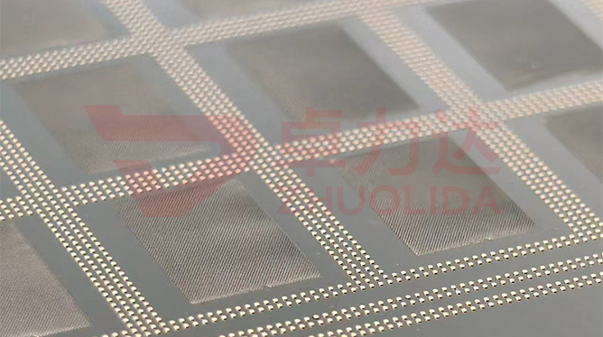
Stray light that one blade cannot block is often handled by stacking a few blades with their openings offset, but stacking adds a variable: how well layer meets layer. Aperture multilayer lamination forming governs how position error accumulates as each opening is registered along one optical axis, and how much shading angle remains once the stack has thickness. It measures not the opening size of one blade but the shift and rotation of each blade against the datum and the light-passing cone angle at full stack thickness, judged on the line by scanning locating marks layer by layer with a vision system and measuring post-stack opening mismatch with flash measurement. Every layer can pass on its own, yet a few microns of drift by the third or fourth layer quietly changes the shading angle and the blocking design comes to nothing.
The trap on the line is treating lamination as the sum of single-blade inspections. On one four-layer lot every blade measured within ±5 μm double-side alignment on its own, but no inter-layer re-check was done after stacking, and the mounted shading angle came out smaller than designed; the cause was locating-hole tolerance drifting the same way layer after layer until four of them added into visible mismatch. On a rushed lot the adhesive layer ran uneven, one blade cocked slightly after pressing, and the inter-layer spacing wandered so the light-passing cone angle drifted with it. More hidden still, no low-temperature anneal was run, inter-layer stress released slowly, and measured two weeks later the shading angle had moved on its own, reported only once the customer mounted it. None of these failures are written into a single-blade 20 μm rib re-check, and by the time they surface the whole stack usually has to come apart for re-registration. Aperture multilayer lamination forming is hard to put into practice precisely because the error is saved up layer by layer, and no single blade shows the running total.
Parameter Window
• Inter-layer alignment: ±5 μm, re-checked against the datum rather than the neighbouring layer
• Fine rib width: 20 μm; stacking mismatch eats the rib margin first
• Single-layer thickness: chosen within the 15–200 μm band, spacing set by shading angle
• Double-side alignment: ±5 μm, with LDI lamination locking each layer's marks in one pass
• Shading angle: upper and lower limits banded by layer count, cone angle measured after stacking
• Locating datum: one set of holes shared across a tiling panel up to 610×660 mm
Manufacturing Process (8 Steps)
1. Stack design — lay out each opening and the stacking order from the target shading angle, budgeting accumulation first.
2. One-master output — put all layers and the locating datum on one master to avoid a second overlay shift.
3. Lamination and LDI — 8 μm/8 μm resolution and ±5 μm double-side alignment form the layer marks in one pass.
4. Development and electroforming — hold undercut, stage 1–4 A/dm², keep each layer inside its thickness band.
5. Demold and flatten — release each blade alone and measure flatness; a cocked blade does not enter the stack.
6. Inter-layer alignment — vision system scans locating marks, registering each layer against the datum.
7. Lamination and anneal — press with controlled adhesive thickness, then a low-temperature anneal relieves inter-layer stress.
8. Post-stack re-check — flash measurement reads shading angle and opening mismatch, with an alignment record per layer.
Core Advantages
1. True shading angle — aperture multilayer lamination forming budgets error per layer, so the stacked angle sits on the design value.
2. Alignment does not pile up — each layer registers to one datum, so deviation is not amplified layer after layer.
3. Stable stack — controlled adhesive plus low-temperature anneal keeps the shading angle from drifting over weeks.
4. Consistent on large panels — a shared datum across 610×660 mm tiling keeps stack-to-stack behaviour even.
5. Traceable — alignment value and adhesive thickness are logged per layer, so a fault reaches back to an exposure or press lot.
6. Easier mounting — the light-passing cone angle is measured before shipping, so the lens group does not retune blocking.
Typical Applications
1. Deep baffle apertures in high-contrast imaging lenses, where multilayers suppress stray light.
2. Cone limiting apertures in laser paths, where the shading angle sets the light-passing cone directly.
3. Stacked multi-ring vignetting apertures, where many layers make accumulated alignment most critical.
4. Composite apertures with 20 μm fine ribs, where stacking mismatch hurts the ribs first.
5. Large-panel tiled multilayer aperture sets, where stack-to-stack behaviour has to match.
6. Instrument apertures needing long-term stability, whose shading angle must not drift after anneal.
Design and Selection Notes
1. Work back from the target shading angle to stacking order and thickness; do not tune the angle after the stack is built.
2. Share one set of locating holes across layers; aligning to the neighbouring layer piles the error up.
3. Give aperture multilayer lamination forming its own station; scanning marks layer by layer cannot be folded into single-blade inspection.
4. Band the adhesive thickness; uneven layers change inter-layer spacing and the shading angle directly.
5. Never stack a cocked blade; flatten it first if flatness is out.
6. Do not skip the low-temperature anneal; unreleased inter-layer stress lets the shading angle drift over time.
7. Measure the light-passing cone angle after stacking; single-blade ±5 μm data cannot cover the running total.
Seen on its own, aperture multilayer lamination forming barely fills a standalone step: each opening's position against the datum is fixed when the master puts the layers out together and LDI locks front to back, development undercut, electroformed thickness and demold flattening each add a little deviation, and adhesive pressing plus low-temperature anneal decide whether those deviations pile up or get absorbed. Inter-layer alignment follows the exposure lot, locating-hole tolerance and adhesive state, so it has to be scanned per layer and re-checked per stack rather than let one clean blade speak for the whole stack. What is hard on a line is not building one stack with a true angle now and then, but keeping a dozen stacks from one lot and several consecutive panels with the shading angle still on the design value at the fourth or fifth layer, only then do 20 μm ribs and ±5 μm alignment become steady blocking. For multilayer, wide-shading-angle or long-stability orders, fix stacking order, locating datum, adhesive thickness and the anneal curve into the process card at sampling stage; running to that card is far cheaper than pulling stacks apart to re-register or reworking after mounting. On paper aperture multilayer lamination forming is a string of per-layer alignment records; on the line it is the plain fact that every stack keeps its shading angle over time and blocks stray light cleanly.
Contact:赖先生
Phone:+86 18938693450
Tel:0755-2708-8292
Email:yw9@zldsmt.com
Add:深圳市宝安区福永镇新和村福园一路华发工业园A3栋
 Zhuolida
