Welcome: Shenzhen Zhuolida Electronics Co.TD
Language:
 ∷

∷
∷
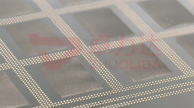
Electroformed aperture opening roundness recheck governs how round the concentric openings on an aperture plate really are. Multi-ring openings nest outward from the centre and should be true circles, yet an electroformed part always carries a little ellipticity, a corner or a local bulge; a few microns off and the clear aperture is no longer the design value, light that should be blocked at the edge is not, and stray light leaks along the out-of-round rim into the optical path, pulling down image contrast. The openings are not drilled: LDI exposes annular windows in the resist, development sets the resist sidewall, and nickel grows against that wall into light-blocking rings. How round they end up is settled in these few steps. Aperture opening true roundness is normally held to ± 0.002 mm, achieved not by downstream polishing, which would snap a 20 μm rib, but by holding roundness at the moment of deposition and then fitting each ring with a vision system while a flash measurement system scans the whole plate. Electroformed aperture ring roundness inspection is hard because there are many rings and thin ribs; measuring one opening proves nothing.
Trouble on the line is usually one ring quietly going out of round. On a camera aperture the centre ring passes roundness recheck, yet the mounted image fogs at the corners; strip it down and the outermost opening has been pulled into a slight ellipse, long axis 3 μm over the short one, and oblique light leaks through exactly that stretch. On a multi-ring mask the 20 μm ribs between rings are squeezed wider by lateral growth during electroforming, roundness still inside tolerance but clear area shrunk a band and measured flux below design; the trail leads to slight resist sidewall collapse in development that made the nickel grow crooked. More costly still is blaming all ovality on demolding: change the lift angle again and again and the opening is a little less elliptic, but the ribs come out with burrs and stray light scatters worse at those burrs. None of these show up in a ± 3 μm aperture accuracy re-check, and by the time the optical path will not align the plate is usually already in the barrel. Electroformed aperture opening roundness recheck is harder to put into practice because roundness is a whole-circle matter: a flat-bed checker scanning apertures at a threshold cannot read an ellipse, so each ring has to be fitted and the whole plate logged.
Parameter Window
• Opening true roundness ± 0.002 mm, fitted ring by ring, never a whole-plate mean
• Aperture accuracy ± 3 μm and position accuracy ± 7 μm, re-checked separately from roundness
• Aperture rib line width 20 μm; ribs must not be squeezed wider by lateral growth or pulled into burrs
• LDI resolution 8 μm/8 μm and double-side alignment ± 5 μm; annular windows are shaped here
• Current density 1–4 A/dm², rings run at the lower end for slow deposition that suppresses edge nodules
• Nickel alloy hardness 450–550 Hv, maximum substrate 610 × 660 mm
Manufacturing Process (8 Steps)
1. Ring artwork — draw the multi-ring opening pattern, flag roundness and rib width per ring.
2. Pre-treatment — clean and make the substrate conductive, passivate the mandrel face to avoid strike nodules.
3. Lamination and LDI — imported LDI exposure at 8 μm/8 μm resolution and ± 5 μm double-side alignment; annular windows take shape here.
4. Development — control concentration and time so the resist sidewall neither collapses nor undercuts; roundness is fixed here.
5. Electroforming — staged control of current density at 1–4 A/dm² and bath temperature holds lateral ring growth in check.
6. Demolding — one-piece release from a low-stress corner; 20 μm ribs are most easily pulled into burrs at lift-off.
7. Inspection — vision system fits roundness per ring, flash system scans rib width and the whole-plate stray-light boundary.
8. Framing and low-temperature anneal — locate with an AB-adhesive frame, relieve stress by low-temperature anneal, then ship by band.
Core Advantages
1. Stray light held off — bring electroformed aperture opening roundness recheck to ± 0.002 mm and corners stop fogging.
2. Flux matches design — steady roundness and un-squeezed ribs keep measured clear area from shrinking.
3. Fine ribs survive — 20 μm rings skip downstream polishing, which would snap a rib.
4. Evidence per ring — fitted roundness logged for every ring, so a fault reaches back to the exposure lot.
5. Whole-plate consistency — exposure set per ring within 610 × 660 mm, so outer rings are no more elliptic than inner ones.
6. Stiff enough — nickel alloy hardness 450–550 Hv keeps rings from deforming under barrel clamping.
Typical Applications
1. Camera and lens apertures, where multi-ring roundness sets corner image quality.
2. Optical metrology masks, where a little stray light drifts the reading.
3. Laser and projection apertures, clear-light boundary held to ± 0.002 mm.
4. Multi-ring bands with 20 μm fine ribs, rib width and roundness checked together.
5. Semiconductor inspection apertures, ± 3 μm aperture accuracy re-checked alongside roundness.
6. Large 610 × 660 mm mask arrays, whole-plate roundness without selection or piecing.
Design and Selection Notes
1. Fix the development band by ring order first. Outer rings are longer and undercut more, so do not copy the inner-ring time.
2. Run ring current at the lower end. Lateral growth squeezes a rib wider and flux drops before roundness goes out.
3. Verify resist sidewall verticality per lot; a slight collapse makes the nickel grow into an ellipse.
4. Fit and log roundness per ring, never hand over a whole-plate mean that hides a few microns at the rim.
5. Fix the release direction at 20 μm ribs; a pulled burr is harder to trace than an ellipse.
6. Recheck double-side alignment at ± 5 μm per plate, or a ring offset gets repaired as if it were ovality.
7. Set anneal temperature to nickel thickness so stress relief does not pull the openings elliptic.
Laid out on a process sheet, electroformed aperture opening roundness recheck has no cell of its own: annular windows are set by LDI exposure, a few seconds of development decide whether the resist sidewall collapses, strike current decides how far nickel rings grow sideways, and the few seconds of release decide whether 20 μm ribs survive. Pre-treatment, exposure, deposition and stripping each own a stretch of it, and let any one slip and the ± 0.002 mm roundness will not hold once mounted. What is hard on a line is not turning out one plate with beautiful roundness now and then, but keeping every fitted ring of a dozen plates from one bath and several consecutive lots inside the same band — only then is electroformed aperture ring roundness inspection more than a phrase. For camera and metrology orders judged on the stray-light boundary, fix exposure dose, development time, the current curve and release direction into the process card at sampling stage and run to that card in production; it is far cheaper than endlessly readjusting the aperture and shimming masks after the barrel is assembled. On paper electroformed aperture opening roundness recheck is a string of parameters; on the line it is the simple fact that every ring of every plate is round enough to block its light.
Contact:赖先生
Phone:+86 18938693450
Tel:0755-2708-8292
Email:yw9@zldsmt.com
Add:深圳市宝安区福永镇新和村福园一路华发工业园A3栋
 Zhuolida