Welcome: Shenzhen Zhuolida Electronics Co.TD
Language:
 ∷

∷
∷
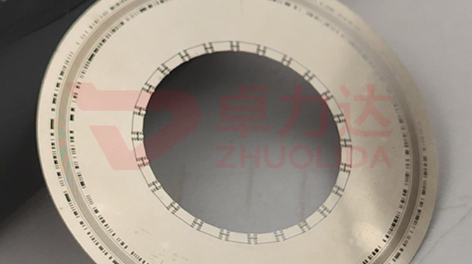
Encoder disc signal duty cycle control governs the width ratio between one light line and one dark line on a code track. On a 50 μm track the ideal is half light and half dark, a 50% duty cycle, so the photodiode reads clean sine waves on A and B and quadrature and interpolation accuracy follow that ratio. The light and dark pattern on an electroformed disc is not printed: LDI opens transparent windows in the resist, development sets the resist sidewall, and nickel grows from the window edge into opaque bars. How wide the clear zone and the bar end up is settled in these few steps. Let the ratio slip, say the light line comes out 2 μm narrow, and the waveform turns asymmetric about zero; interpolation error follows, and on the machine it shows up as index jitter and low-speed creep. Disc light-dark duty cycle recheck uses a vision system to measure line width track by track and a flash measurement system to scan whole-disc consistency, so electroformed disc signal waveform consistency means every track lands in the same band, not a mean taken from a few sampled spots.
The usual trouble on the line is not that the track fails to form, but that the light-dark ratio drifts quietly. On an incremental disc the 50 μm track measures inside ± 0.5 μm on line width, yet after mounting the A phase amplitude sits below B; the scope shows a waveform asymmetric about zero, and the trail leads to a few seconds of extra development time that undercut the transparent window by a ring and pulled duty cycle down to 47%. On an absolute disc the inner tracks are fine while the outer ones drift further out, traced to an aggressive strike current that let lateral nickel growth widen the opaque bars, with current density already higher at the rim. More subtle still: fine particles in the bath grow nodules along a bar edge, so local duty cycle jumps up and down, the signal carries glitches as the disc turns, and the interpolation counter occasionally skips one count. None of these show up in a ± 7 μm line-position re-check, and by the time the customer mounts the disc a whole wafer has usually been diced. Encoder disc signal duty cycle control is harder to put into practice than dimensional inspection because it governs a width ratio rather than a single line size, and a flat-bed stencil checker scanning openings at a fixed threshold cannot read ratio drift; the tracks have to be overlaid and measured one by one.
Parameter Window
• Track 50 μm ± 0.5 μm, light and dark line widths re-measured track by track
• Duty cycle 50% ± 2% as the delivery window, held to ± 1% internally
• LDI resolution 8 μm/8 μm and double-side alignment ± 5 μm; clear-zone width is set here
• Current density 1–4 A/dm², outer tracks run at the lower end to stop lateral growth widening bars
• Nickel alloy hardness 450–550 Hv; when hardness is raised, watch internal stress and edge nodules alongside
• Maximum substrate 610 × 660 mm, exposure dose and current set per track across the disc
Manufacturing Process (8 Steps)
1. Track artwork — draw the light-dark bar pattern, flag duty cycle requirements for each 50 μm track.
2. Pre-treatment — clean and make the substrate conductive, passivate the mandrel face to avoid strike nodules.
3. Lamination and LDI — imported LDI exposure at 8 μm/8 μm resolution and ± 5 μm double-side alignment; the clear zone takes shape here.
4. Development — control concentration and time so windows are not undercut and light-dark widths are fixed here.
5. Electroforming — staged control of current density at 1–4 A/dm² and bath temperature holds lateral bar growth in check.
6. Demolding — one-piece release from a low-stress corner; fine bars are most easily stretched wider at lift-off.
7. Inspection — vision system measures line width per track and computes duty cycle, flash system scans waveform consistency across the disc.
8. Framing and low-temperature anneal — locate with an AB-adhesive frame, relieve stress by low-temperature anneal, then ship by tension band.
Core Advantages
1. Symmetric waveform — hold encoder disc signal duty cycle control at 50% ± 2% and A/B amplitudes match.
2. No skipped counts — a steady ratio cuts low-speed creep and count jumps.
3. Whole-disc consistency — exposure set per track within 610 × 660 mm, so outer tracks do not drift more than inner ones.
4. No matching — no need to pair discs with read heads by selection; a lot goes straight onto the machine.
5. Traceable — line width and duty cycle logged per track, so a fault reaches back to the exposure lot.
6. Stiff enough — nickel alloy hardness 450–550 Hv keeps tracks from collapsing at high rotational speed.
Typical Applications
1. Incremental optical encoder discs, where A/B duty cycle sets quadrature directly.
2. Absolute multi-track discs, where inner and outer ratios must converge track by track.
3. Servo motor feedback discs, where low-speed smoothness is most sensitive to waveform symmetry.
4. Robot joints and CNC machine encoders, interpolation error held to ± 0.5 μm.
5. Optical metrology and rotary gratings, where a stray waveform leaks into the angle reading.
6. Composite discs with 20 μm aperture ribs, rib width and track alignment checked together.
Design and Selection Notes
1. Fix the development band by track position first. Outer tracks are longer and undercut more, so do not copy the inner-track time.
2. Run the outer current at the lower end. Lateral growth widens a bar and the ratio shifts toward the dark zone.
3. Do not skip bath filtration. A particle landing on a bar edge is a local ratio glitch.
4. Measure window width after development before the bath; resist undercut cannot be recovered downstream.
5. Log duty cycle per track, never hand over a whole-disc mean that hides a few points at the rim.
6. Fix the release direction and do not change the lift angle; a stretched bar is harder to trace than a line out of tolerance.
7. Set anneal temperature to nickel thickness so stress relief does not pull track spacing out of shape.
Seen on its own, encoder disc signal duty cycle control barely occupies a standalone step: clear-zone width is set by LDI exposure, a few seconds of development decide whether the window is undercut narrow, strike current decides how far nickel bars grow sideways, and the few seconds of release decide whether fine lines survive. Pre-treatment, exposure, deposition and stripping each own a stretch of it, and let any one slip and the 50% ± 2% ratio will not hold. What is hard on a line is not turning out one disc with a clean waveform now and then, but keeping every track of a dozen discs from one bath and several consecutive lots inside the same duty-cycle band — only then does electroformed disc signal waveform consistency mean anything. For servo and robotics orders judged on interpolation accuracy, fix exposure dose, development time, the current curve and release direction into the process card at sampling stage and run to that card in production; it is far cheaper than endlessly retuning read-head thresholds and pairing discs after mounting. On paper encoder disc signal duty cycle control is a string of parameters; on the line it is the simple fact that every disc turns with A and B symmetric.
Contact:赖先生
Phone:+86 18938693450
Tel:0755-2708-8292
Email:yw9@zldsmt.com
Add:深圳市宝安区福永镇新和村福园一路华发工业园A3栋
 Zhuolida