Welcome: Shenzhen Zhuolida Electronics Co.TD
Language:
 ∷

∷
∷
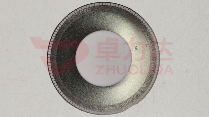
The aperture at the tip of an endoscope has a rib and line width of only 20 μm, walls that must be near vertical and a root with no corner radius. Burr-free aperture blade straight wall forming is what produces such a thin-walled structure in one go: nickel grows vertically along the resist sidewall on the mandrel, so however straight the resist mould is, that is how straight the finished wall is, with a surface smooth enough to skip post-machining. It is a different route from etching — etching bites metal away with chemistry and inevitably undercuts the sidewall into a curve and leaves a radius at the corner; electroforming grows metal into the voids of the mandrel, replicating its three-dimensional shape, so a 20 μm rib, thin walls and complex profiles all transfer across. Substrates from 0.03–5 mm all work, LDI resolution of 8 μm/8 μm decides whether a 20 μm rib can stand, and development and demolding are where 20 μm rib width really gets difficult.
Why etching cannot give a straight wall starts with the chemistry. Wet etching is isotropic: as the etchant drills down it also eats sideways, and the finer the rib the larger the share of undercut — a 20 μm line width cannot survive a few microns taken off each side. At corners the field and flow effects combine, a rounded corner radius is almost unavoidable, the finished wall turns trapezoidal and the aperture's light section distorts with it. Electroforming reverses this: LDI first builds a 20 μm wide resist cavity on the substrate, nickel ions reduce only on the exposed conductive face and grow upward layer by layer along the resist wall; a near-vertical resist sidewall gives a near-vertical metal wall, and the corner radius is set by the mandrel rather than by the etchant. The difficulty moves to development and demolding. A 20 μm resist rib with a large height-to-width ratio tends to swell, collapse or leave residue in developer, and a tilted rib means a tilted wall; at release such a fine nickel rib has almost no stiffness, so a slightly wrong start angle or speed bends or snaps it. That is why 8 μm/8 μm LDI resolution is only the entry ticket — development time, resist bake, release support and low-stress deposition have to come together as one set before a radius-free straight wall at 20 μm rib width lands on a real part.
Parameter Window
• Rib and line width 20 μm, walls near vertical and the root free of corner radius
• Substrate thickness 0.03–5 mm, thin-walled structures copied from the mandrel's three-dimensional shape
• LDI resolution 8 μm/8 μm, deciding whether a 20 μm resist rib can stand
• Surface copies mandrel finish, so no post-machining after forming
• Development and demolding are the key control points at 20 μm rib width, guarding against collapse and bending
• Nickel alloy hardness 450–550 Hv, hardness weighed with internal stress on thin-walled parts
Manufacturing Process (8 Steps)
1. Artwork preparation — master data from the light-hole pattern, with development allowance for the 20 μm rib width.
2. Pre-treatment — cleaning and conductive coating of 0.03–5 mm substrates, with low-adhesion passivation of the mandrel face.
3. Lamination and LDI — imported LDI exposure at 8 μm/8 μm resolution, building the 20 μm resist cavity.
4. Development and electroforming — controlled development time and resist bake, nickel growing vertically along the wall to fill the cavity.
5. Demolding — start from a low-stress edge with support, control angle and speed for one-piece release, fine ribs left intact.
6. Resist stripping — remove the resist to expose near-vertical 20 μm ribs and the radius-free root.
7. Inspection — vision system measures rib width and wall angle, confirming no undercut arc and no machining needed.
8. Cutting and packing — cut to aperture outer diameter with rib-width and wall-angle readings.
Core Advantages
1. Straight-wall forming — mandrel plus vertical growth gives near-vertical 20 μm walls with no corner radius at the root.
2. No machining — the surface copies mandrel finish, so thin-walled parts skip secondary cutting and deburring.
3. Three-dimensional replication — complex profiles and thin walls transfer from the mandrel in one step, beyond etching.
4. Accurate light section — no tapered undercut wall, so an endoscope aperture matches its design clear opening.
5. Fine ribs intact — collapse-proof development and supported release keep 20 μm ribs from bending or snapping.
6. Batch consistency — several parts from one 0.03–5 mm substrate share a bath, with wall angle and rib width traceable.
Typical Applications
• Medical endoscope apertures, where 20 μm straight walls keep the light section from distorting.
• Optical instrument field stops, where a radius-free root cuts stray reflection.
• Precision inspection shading masks, thin walls formed on the 0.03 mm minimum substrate.
• Semiconductor and sensor masks, complex three-dimensional profiles copied once from the mandrel.
• Laser and imaging system apertures, surfaces assembled directly with no machining.
• Composite apertures with local thickening, where release direction avoids the thickened step root.
Design and Selection Notes
1. Confirm etching or electroforming first. For straight walls with no corner radius, the etching route is basically closed.
2. Pair 20 μm rib width with 8 μm/8 μm resolution and leave resist-swelling allowance in the master artwork.
3. Choose 0.03–5 mm substrate by assembly stiffness; very thin stock needs full support through release.
4. Control development time and bake for high-aspect-ratio resist ribs, or they collapse in the liquid.
5. Do not chase hardness. 450–550 Hv is sufficient; pushing it up raises internal stress in fine ribs.
6. The 8 μm/8 μm LDI resolution belongs to exposure; wall-angle re-measurement after stripping is the delivery figure.
7. For apertures with thickening or shaped profiles, choose a release direction away from step roots and dense fine-rib zones.
Explaining burr-free aperture blade straight wall forming properly is less about the verdict 'electroforming beats etching' than about which step lets the deviation in. Etching's corner radius and undercut come from isotropic chemistry; changing the recipe can only reduce them, never remove them. Electroforming hands the wall shape to the mandrel resist wall and grows nickel vertically, so a corner radius is never generated at source. But 20 μm rib width simply moves the problem elsewhere: resist ribs collapse in developer and nickel ribs bend at release, and 8 μm/8 μm resolution only guarantees the part can be made, not that it can be lifted off. That is exactly where burr-free aperture blade straight wall forming belongs in the process card — development time, resist bake, release support and low-stress deposition have to fit one set of numbers, and miss one item and a straight wall turns trapezoidal. What separates capable lines is not whether an aperture can be grown on a 0.03–5 mm substrate, but whether a dozen parts from one bath all finish on the same wall angle. For endoscope apertures accepted on a micron-level light section, fix master compensation, the development window and release angle at sampling stage. Aperture blade rib width control and electroformed aperture straight wall forming go by different names, yet on the shop floor both come down to one thing: making burr-free aperture blade straight wall forming a parameter whose wall angle can be measured on every part.
Contact:赖先生
Phone:+86 18938693450
Tel:0755-2708-8292
Email:yw9@zldsmt.com
Add:深圳市宝安区福永镇新和村福园一路华发工业园A3栋
 Zhuolida