Welcome: Shenzhen Zhuolida Electronics Co.TD
Language:
 ∷

∷
∷
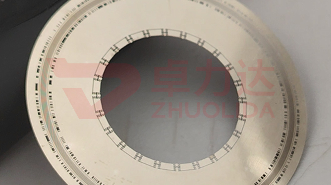
An electroformed encoder disc of 30–200 μm has code tracks whose narrowest rib and slot are only 50 μm, at ±0.5 μm, and the whole part still has to stay flat within 0.2 mm. Encoder disc flatness control is exactly that: replicating that ring of 50 μm tracks one-to-one from the mandrel while keeping the nickel layer from curling or bowing after release, holding flatness below 0.2 mm, roundness tolerance at ±0.002 mm and hardness on whichever HV400–550 band the order calls for. It is not a single flattening step but the balance point reached when internal stress, code-track replication fidelity and hardness customisation pull against each other: push hardness up and stress tends to follow; once stress rises the thin disc warps, and flatness and track position fail together.
Of the three, internal stress is the one most often underestimated. Add too much brightener and the grain refines, hardness moves toward HV550 and residual stress climbs with it; raise current density from 1 to 4 A/dm² and the deposition rate spreads between the disc edge and centre, turning a thickness difference into an in-plane stress difference. None of it shows while the disc is still on the mandrel, clamped by a rigid substrate. Release it and the constraint disappears; stress lets go at once, a 30 μm disc can bow into a visible wave on the spot, flatness breaks 0.2 mm and even the pitch of the narrowest 50 μm track is stretched with it. Replication fidelity is the other end: a 50 μm±0.5 μm rib and slot on the mandrel only survives through LDI resolution of 8 μm/8 μm, ±5 μm double-side alignment and controlled development — over-develop by a little and the rib thins while the slot widens. Hardness customisation tugs at both: a soft HV400 disc flattens easily but wears faster, while a hard HV550 disc lasts longer yet fights flatness. So the line is not tuning one number; it is fitting anneal temperature, brightener concentration and strike current density into one set that lets 0.2 mm flatness, 50 μm tracks and target hardness all pass at once.
Parameter Window
• Disc thickness 30–200 μm; below 50 μm flatness is most sensitive to stress release
• Narrowest code-track rib and slot 50 μm±0.5 μm, accepted against post-release vision measurement
• Flatness below 0.2 mm and roundness tolerance ±0.002 mm logged for the same lot
• Hardness HV400–550 customised to order, the hardness band weighed against internal stress
• LDI resolution 8 μm/8 μm, double-side alignment ±5 μm, substrates up to 610×660 mm
• Low-temperature anneal after release removes stress so dimensions stay put after assembly
Manufacturing Process (8 Steps)
1. Artwork preparation — master data from the track pitch, with development-undercut allowance for the 50 μm rib and slot.
2. Pre-treatment — substrate cleaning and conductive coating, with low-adhesion passivation of the mandrel face.
3. Lamination and LDI — imported LDI exposure at 8 μm/8 μm resolution, ±5 μm double-side alignment, substrates up to 610×660 mm.
4. Development and electroforming — set brightener and current density to the target hardness band after development, keeping stress down as the layer grows.
5. Demolding — start from a low-stress corner, control angle and speed for one-piece release, support thin discs before lifting.
6. Stress relief — low-temperature anneal removes residual stress and settles flatness inside 0.2 mm.
7. Inspection — vision system reads the 50 μm tracks and ±0.002 mm roundness; flatness stage and hardness tester confirm the HV band.
8. Cutting and packing — cut to assembly outer diameter with per-sheet flatness, track and hardness readings.
Core Advantages
1. Flatness holds — low-stress deposition plus low-temperature anneal keeps a 30 μm disc from bowing after release.
2. Track fidelity — 50 μm±0.5 μm ribs and slots are replicated once by mandrel and LDI, with no blurred development edges.
3. Hardness on order — HV400–550 adjustable in bands, both soft and hard grades accepted together with flatness.
4. True roundness — ±0.002 mm locked at the mandrel stage, so assembly concentricity needs no second correction.
5. Batch consistency — several discs from one 610×660 mm panel share stress conditions, narrowing disc-to-disc spread.
6. Complete data — flatness, track width and hardness band logged per disc; anomalies trace back to the bath run.
Typical Applications
• Servo-motor encoders, where 50 μm tracks paired with 0.2 mm flatness keep readings stable.
• Lidar scanning discs, where low stress stops a thin disc warping as temperature rises.
• Absolute encoder discs, with HV400–550 chosen for the shaft load.
• Counter discs in computer accessories and precision hardware, used directly at ±0.002 mm roundness.
• Code discs for toy hardware, where a lower hardness band balances cost and formability.
• Composite discs with local thickening, where release direction avoids the step root.
Design and Selection Notes
1. Fix thickness and hardness band first. Discs of 30–50 μm are better at HV400–450 than chased up to HV550.
2. State whether flatness is post-release or post-anneal; below 0.2 mm refers to the delivered state.
3. Verify the 50 μm±0.5 μm track tolerance line by line on a vision system, not just on the outer ring.
4. Discuss hardness band and flatness together; assess the stress margin before raising hardness.
5. Leave development-undercut allowance in the master artwork and write ±0.002 mm roundness into the drawing.
6. The ±5 μm double-side figure belongs to exposure; post-release track re-measurement is the delivery figure.
7. Set anneal temperature by hardness band and never mix bands in one lot, or disc-to-disc flatness will differ.
Seen on its own, encoder disc flatness control is less about pressing a disc flat than about keeping internal stress, track fidelity and hardness customisation from undercutting one another. Low-temperature anneal bleeds off stress so 0.2 mm flatness can stand; mandrel and LDI copy the 50 μm±0.5 μm rib and slot one-to-one so the track reads true; and whichever HV400–550 band is chosen feeds back into how hard the first two become. That is exactly why encoder disc flatness control so easily turns into a list of applications — mention discs and out come motors, lidar and computer accessories, with few explaining how warp grows out of the bath in the first place. What separates capable lines is not whether a 30–200 μm disc can be plated, but whether a dozen discs from one bath all finish on the same flatness numbers. For lidar and servo-motor read-out orders, fix brightener concentration, strike current density, anneal temperature and hardness band into the process card at sampling stage. Electroformed disc code-track accuracy control and precision disc hardness customisation go by different names, yet on the shop floor both come down to one thing: making encoder disc flatness control a parameter every disc can be measured, signed and repeated against.
Contact:赖先生
Phone:+86 18938693450
Tel:0755-2708-8292
Email:yw9@zldsmt.com
Add:深圳市宝安区福永镇新和村福园一路华发工业园A3栋
 Zhuolida