Welcome: Shenzhen Zhuolida Electronics Co.TD
Language:
 ∷

∷
∷
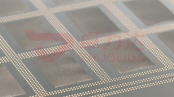
A stencil aperture cut to perfection is wasted paste if it does not land right over the pad. Electroformed stencil printing overlay compensation control owns that gap: once the foil is stretched onto its aluminium frame and mounted on the printer, the aperture coordinate system and the PCB pad coordinate system always carry some translation, rotation and scaling, summing to a pattern offset of a few microns. The control does not touch the printer's alignment cameras; it breaks the offset apart instead — the datum error left by ±5 μm LDI double-side alignment, the positional drift pulled in by 10–55 N stretching, and substrate expansion are each measured, then a reverse shift is written into the master data or the print program up front. A vision system reads MARK fiducials and flash measurement re-checks overlay deviation at the end, confirming ±7 μm position accuracy is pulled inside the band. What gets compensated is position, not aperture size, which is exactly where this differs from dimensional compensation.
The most common line-side mistake is treating alignment as a one-off camera tweak at setup. One BGA stencil had its MARK fiducials lined up perfectly, yet the first-article edge pads still ran past ±7 μm; the cause was stretching tension pushed to 55 N with nickel-foil elastic elongation never booked into the master coordinates, so the centre held and the rim drifted cumulatively. Another lot moved to a 610×660 mm board, substrate expansion followed shop temperature, and the same program printed two different offsets in the morning and afternoon because overlay-deviation re-measurement was never scheduled into the flow. Sneakier still is trusting only the first article: across a 15000-print life, frame creep and AB adhesive stress release slowly ease the pattern a few microns by the time several thousand boards are done, with early boards clean and later ones bridging. Then there is treating ±5 μm LDI double-side alignment as a universal budget, which stacking with stretch drift eats the ±7 μm allowance outright. None of these are a crooked aperture; they are a position that was never compensated right. Electroformed stencil printing overlay compensation control is set up as its own item because the offset moves with tension, substrate and print count, and no single compensation value lasts forever.
Parameter Window
• Position accuracy ±7 μm; the target band the printing overlay compensation converges to
• LDI double-side alignment ±5 μm and 8 μm/8 μm resolution; datum error starts from here
• Tension 10–55 N with ±1 N in-house control; elastic elongation estimated in thickness bands
• Maximum substrate 610×660 mm; larger spans show more cumulative edge offset
• Ball-placement template total pitch ±7 μm; overlay-deviation re-measurement is read against this
• Print life 15000 cycles; offset re-drift spot-checked by print count through the run
Manufacturing Process (8 Steps)
1. Coordinate alignment — bring master data, stencil MARK fiducials and the PCB pad map onto one datum.
2. Drift estimate — compute stretch elongation from the 10–55 N band and thickness, reserve it in the data.
3. Lamination and LDI — output at 8 μm/8 μm resolution, double-side alignment ±5 μm, log this lot's datum error.
4. Stretch and locate — AB adhesive to the frame, corner marks aligned, re-measure MARK coordinates.
5. First-article re-check — vision system reads pad-to-aperture offset, flash measurement sweeps overlay deviation.
6. Compensation entry — write translation, rotation and scaling into the print program or back into master data.
7. Print-count sampling — spot-check at nodes across 15000 cycles to see whether offset drifts back with creep.
8. Release and trace — re-compensate anything past ±7 μm, archive compensation values and re-check records per lot.
Core Advantages
1. Offset made calculable — electroformed stencil printing overlay compensation control deducts stretch drift and datum error item by item.
2. Edges hold too — 610×660 mm span drift is compensated on its own, not just centre-aligned.
3. Budget protected — ±5 μm double-side alignment is not quietly eaten by stretching, so ±7 μm stays.
4. Stable through the run — print-count sampling catches creep re-drift, no late-run failure inside 15000 cycles.
5. Fast changeover — a new thickness runs a drift estimate instead of trial prints on the machine.
6. Traceable — each lot stores compensation values, overlay re-checks and MARK coordinates down to the batch.
Typical Applications
1. Mini LED and BGA fine-pitch printing stencils, where small pads cannot afford a ±7 μm offset.
2. WLP ball-placement templates for 4–12 inch wafers, where a 30 μm minimum aperture must sit right on the pad.
3. Ball and Flux stencils for ABF substrates, where double-side alignment leans on overlay re-measurement.
4. 610×660 mm photovoltaic large meshes, where cumulative edge offset grows with span.
5. Semiconductor grading micro-aperture screens, where a ≥50 μm web cannot take over-compensated positions.
6. Composite stencils with local thickening, where step stress concentration needs banded drift compensation.
Design and Selection Notes
1. Unify the master, MARK fiducials and pad map on one datum first, do not back-solve coordinates at the machine.
2. Estimate stretch drift by the 10–55 N band; a thin foil must not borrow a thick foil's elongation.
3. Book ±5 μm double-side alignment and ±7 μm position apart, so a fault traces to exposure or stretching.
4. Sweep overlay deviation on the first article with flash measurement, do not trust only the printer's MARK readout.
5. Lock the version once compensation is written, recompute each new lot, never ship with the last lot's values.
6. Set sampling nodes across the 15000-cycle life; stop and re-compensate if creep re-drift passes ±7 μm.
7. Log shop temperature and humidity on the lot card, since substrate expansion shifts by season and compensation follows.
Seen in isolation, electroformed stencil printing overlay compensation control adds no machining step; it all rests on the compensation. The datum is unified in the master data, how far stretching drags the pattern is cleared in the drift estimate, the first article reads actual overlay deviation back through a vision system and flash measurement, and only then does the compensation value land in the print program — after which print-count sampling still has to watch creep re-drift. Let any segment be measured once and treated as a constant and ±7 μm position accuracy will eventually be breached by edge drift or late-run re-drift. What is hard on a line is not a clean first article, but holding centre-to-edge apertures over the pads from several consecutive lots and from the first board to the 15000th — only then does fine pitch dare go toward ≥25 μm. For orders with a hard alignment requirement, freeze the datum layout, tension-to-drift table, first-article overlay re-check rule and print-count sampling nodes into the process card at sampling and run to that card in production; it is far cheaper than finding bridging at the printer and re-tuning cameras against trial compensation values. On paper electroformed stencil printing overlay compensation control is a few translation-rotation figures and one drift curve; on the line it is the fact that every board prints with apertures stopping right over their pads, with no rescue alignment needed.
Contact:赖先生
Phone:+86 18938693450
Tel:0755-2708-8292
Email:yw9@zldsmt.com
Add:深圳市宝安区福永镇新和村福园一路华发工业园A3栋
 Zhuolida