Welcome: Shenzhen Zhuolida Electronics Co.TD
Language:
 ∷

∷
∷
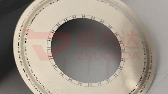
An incremental encoder reading a 50 μm code track puts out a duty cycle that wanders wide and narrow; line width checks out, pitch checks out, and most likely the line edge never stood up. Encoder disc line edge control governs the shape of the nickel wall at the light-to-dark boundary: LDI and development set the steepness of the resist wall, electroforming copies that wall into metal, and whether the edge carries burrs or the sidewall has slumped into a slope decides how clean the optoelectronic transition is. It is a separate matter from re-checking the 50 μm ± 0.5 μm track dimension — size can be right while a slumped edge still drifts the A/B phase. When aperture rib width comes down to 20 μm the sidewall is a large share of the feature, so edge condition is tighter than line width itself.
Three failures dominate on the line. The first is burrs: a batch of discs jitters at low speed after mounting, and the vision system finds a few 3–5 μm nickel whiskers hanging off the 50 μm track edge, stretching the dark zone at random so duty cycle swings between 45% and 55%. The second is a slumped wall: over-developed resist is undercut into a gentle ramp, copied into nickel as a sloping edge that drags a 2 μm transition onto the rising edge, and high-speed counting drops pulses. The third is misalignment: ±5 μm double-side alignment is not held, front and back lines shift half a cell, and the two phases will not overlap near index. None of these appear in ±3 μm aperture accuracy or a line-width sample, and by the time they surface the disc is usually already bonded to a motor shaft. Disc track edge burrs have to be caught after development and before electroforming, which is exactly why encoder disc line edge control is harder to put into practice than dimensional inspection.
Parameter Window
• Track pitch: 50 μm ± 0.5 μm, paired with 20 μm aperture rib width
• LDI resolution 8 μm/8 μm and double-side alignment ±5 μm; resist wall steepness is set here
• Position accuracy ±7 μm and aperture accuracy ±3 μm, re-checked apart from edge condition
• Edge burrs: mirror inspection per sheet after development, transition judged at the 8 μm resolution band
• Current density 1–4 A/dm², nickel-cobalt alloy hardness 450–550 Hv
• Substrate up to 610×660 mm; in-plane edge consistency sampled by zone
Manufacturing Process (8 Steps)
1. Artwork preparation — master data from the track count, 50 μm tracks and index slot on separate layers.
2. Pre-treatment — substrate cleaning and conductive coating, mandrel passivation so strike nodules miss the line edges.
3. Lamination and LDI — imported LDI exposure at 8 μm/8 μm resolution and ±5 μm double-side alignment; wall steepness is set here.
4. Development — control concentration and time so no residue stays at the foot and the sidewall is not undercut; edge profile is decided here.
5. Electroforming — staged current density of 1–4 A/dm² with the bath held, suppressing edge nodules and burrs.
6. Release — one-piece lift-off from a low-stress corner; the finest line edge scores most easily.
7. Inspection — checker for openings, vision and flash measurement for pitch, mirror check per sheet for edge burrs.
8. Anneal and packing — low-temperature annealing to relieve stress, RoHS cleaning, then filing by sheet number.
Core Advantages
1. Clean edge — encoder disc line edge control keeps the resist wall steep, so the transition does not drag and duty cycle holds.
2. Fewer lost pulses — no burrs and no ramps at the edge, so phase drifts slowly at high count rates.
3. No downstream trimming — 20 μm aperture ribs skip mechanical buffing, so polishing does not eat the line width.
4. Dimensions and edge tracked apart — line width to the checker, sidewall and burrs to the vision system, so a fault pins to a bath run.
5. Two faces consistent — ±5 μm alignment logged per lot, so front and back lines do not shift a cell.
6. Traceable — current density, development time and edge inspection logged per bath, reaching back to the solution lot.
Typical Applications
1. Incremental optical encoder discs, where a 50 μm track is most sensitive to edge condition.
2. Servo motor feedback discs, where low-speed jitter usually comes from line burrs.
3. Absolute encoder multi-track discs, where inner and outer ring edge consistency matters more.
4. Aperture and beam-splitter plates, where 20 μm ribs rely on a steep wall for the light ratio.
5. Compact robot-joint encoders, with dense tracks and a high edge share.
6. High-line-count precision angle discs, where edge condition around the full circle sets interpolation accuracy.
Design and Selection Notes
1. Set track pitch from line count first, then LDI exposure dose; do not reuse coarse-line settings on a 50 μm track.
2. Do not rush development; a few tenths of a micron of undercut becomes a permanent ramp on the nickel wall.
3. Give edge burrs their own station; a flat-bed checker cannot read a slumped sidewall angle.
4. Run 1–2 A/dm² slow deposition; at 550 Hv the edge nodules arrive together with hardness.
5. Re-check ±5 μm double-side alignment per lot; a front-to-back shift is worst near index.
6. Choose a release direction that avoids the root of the finest line, the spot most likely to pull a nickel whisker.
7. On large 610×660 mm substrates inspect by zone; centre and corner edge condition often differ.
Seen on its own, encoder disc line edge control barely occupies a standalone step: LDI and development set the steepness of the resist wall, grain grows as it will in the bath, and the few seconds of release decide whether a fine edge picks up a burr. Pre-treatment, exposure, deposition and stripping each own a stretch, and let any one slip and no 50 μm ± 0.5 μm dimensional re-check will buy back a clean transition. What is hard on a line is not turning out one crisp-edged disc now and then, but keeping a dozen sheets from one bath and several consecutive lots inside the same edge band on both faces — only then does ±7 μm position accuracy mean anything. For orders with hard requirements on high count rates and low jitter, fix exposure dose, development time and the current-density curve into the process card at sampling stage and run to that card; it is far cheaper than endlessly retuning comparator thresholds and adding filtering at the encoder. On paper encoder disc line edge control is two words, steepness and burrs; on the line it is the simple fact that A/B waveforms stay symmetric on every disc that spins.
Contact:赖先生
Phone:+86 18938693450
Tel:0755-2708-8292
Email:yw9@zldsmt.com
Add:深圳市宝安区福永镇新和村福园一路华发工业园A3栋
 Zhuolida
