Welcome: Shenzhen Zhuolida Electronics Co.TD
Language:
 ∷

∷
∷
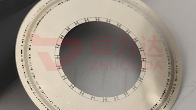
An incremental encoder gives one index pulse per revolution, and the angular relation between that pulse and the A/B tracks is set by a single slot on the disc. Electroformed encoder disc index mark forming governs how that datum slot is made: not a shade stuck on after electroforming, not a laser mark cut downstream, but the single slot and the 50 μm tracks drawn on the same master and grown together in one LDI pass and one electroforming run. That way no second-fixturing angle error sits between index and tracks, and datum mark accuracy is decided by the master and ±5 μm double-side alignment. It is logged separately from re-checking the 50 μm ± 0.5 μm track dimension — slot width is easy to measure, but keeping the slot at the same relative angle to the full circle of tracks on every sheet is the hard part.
Three failures dominate on the line. The first is a bonded-slot angle error: a lot gets its index shade glued on, and after mounting the index pulse sits half a track off the A rising edge, so servo homing misses by dozens of counts every time and the only rework is re-bonding the whole batch. The second is downstream scoring: a laser cuts a slot beside a 20 μm aperture rib, the heat-affected zone burns burrs into the neighbouring line edge, and disc track edge burrs arrive together with index error. The third is double-side drift: front and back made separately, the index slot and back-side tracks shift beyond ±5 μm, and the read head cannot overlap the two phases near index. None of these appear in ±3 μm aperture accuracy or a slot-width sample, and by the time they surface the disc is usually already inside the encoder housing. Electroformed encoder disc index mark forming is harder to put into practice than downstream machining because datum and tracks have to be treated as one and the same pattern.
Parameter Window
• Track pitch: 50 μm ± 0.5 μm, index slot and tracks formed on one master in one run
• Aperture rib width 20 μm, slot-to-rib spacing set by track phase
• LDI resolution 8 μm/8 μm and double-side alignment ±5 μm; datum angle is fixed here
• Position accuracy ±7 μm and aperture accuracy ±3 μm, re-checked apart from index angle error
• Current density 1–4 A/dm², nickel-cobalt alloy hardness 450–550 Hv
• Substrate up to 610×660 mm; full-circle datum consistency sampled by quadrant
Manufacturing Process (8 Steps)
1. Artwork preparation — single slot and 50 μm tracks drawn on one master, index phase angle flagged.
2. Pre-treatment — substrate cleaning and conductive coating, mandrel passivation so strike nodules miss the slot edge.
3. Lamination and LDI — one imported LDI exposure at 8 μm/8 μm resolution and ±5 μm double-side alignment.
4. Development — control concentration and time so slot wall and tracks take shape together, no residue left.
5. Electroforming — slot and tracks grown in the same bath at once, staged current density of 1–4 A/dm².
6. Release — one-piece lift-off from a low-stress corner; the fine slot root scores most easily.
7. Inspection — checker for openings, vision and flash measurement for pitch and index angle error.
8. Anneal and packing — low-temperature annealing to relieve stress, RoHS cleaning, then filing by sheet number.
Core Advantages
1. No assembly angle error — electroformed encoder disc index mark forming grows datum and tracks together, so homing does not rely on a bonded shade being aligned.
2. Stable datum — index angle comes from the master, ±5 μm alignment holds it, and lots do not drift.
3. No neighbour damage — no downstream laser, so no heat-affected burrs beside a 20 μm aperture rib.
4. Dimensions and angle tracked apart — line width to the checker, index phase to the vision system, so a fault pins to a bath run.
5. Traceable — master number, exposure dose and measured index angle logged per sheet, not from memory.
6. Fits first time — the encoder housing needs no allowance for aligning a second bonded part, so assembly takt shortens.
Typical Applications
1. Incremental encoder homing discs, where index pulse and A/B phase must lock together.
2. Servo motor feedback discs, where power-on homing repeatability rests on the single-slot datum.
3. Absolute encoder multi-turn discs, where index and inner tracks sharing one datum saves trouble.
4. Robot-joint encoders, whose housings are too small for a bonded shade.
5. High-line-count angle discs, where full-circle index repeatability is tighter than slot width.
6. Discs paired with grating read heads, where datum and tracks formed together align more truly.
Design and Selection Notes
1. Slot and tracks must share one master; two drawings hand the angle error straight to the fixturing.
2. Fix the index phase angle before laying out tracks; do not squeeze a slot in after the tracks are drawn.
3. Re-check ±5 μm double-side alignment per lot; a front-to-back shift is worst near index.
4. Do not rush development; a little undercut on the slot wall slumps the index edge along with the tracks.
5. Run 1–2 A/dm² slow deposition so grain at the slot floor matches the tracks.
6. Choose a release direction that avoids the slot root, the thinnest section and the one most likely to pull a nickel whisker.
7. On large 610×660 mm substrates sample index angle by quadrant; centre and corners often differ.
Seen on its own, electroformed encoder disc index mark forming barely occupies a standalone step: slot and tracks are laid out at one phase on one master, a single LDI exposure fixes their position, development shapes slot wall and tracks together, the same nickel grows both in one bath, and the few seconds of release decide whether the fine slot root is scored. Split any one of those into two steps and angle error goes straight back to fixturing and bonding. What is hard on a line is not turning out one disc with a true index, but keeping a dozen sheets from one bath and several consecutive lots inside the same band for the relative angle of index and tracks — only then does ±7 μm position accuracy mean anything. For orders with a hard requirement on homing repeatability, fix master phase, exposure dose, development time and the current-density curve into the process card at sampling stage and run to that card; it is far cheaper than retuning the read head and aligning a bonded shade at assembly. On paper electroformed encoder disc index mark forming is two words, one master and one run; on the line it is the simple fact that every disc homes to the same count.
Contact:赖先生
Phone:+86 18938693450
Tel:0755-2708-8292
Email:yw9@zldsmt.com
Add:深圳市宝安区福永镇新和村福园一路华发工业园A3栋
 Zhuolida
