Welcome: Shenzhen Zhuolida Electronics Co.TD
Language:
 ∷

∷
∷
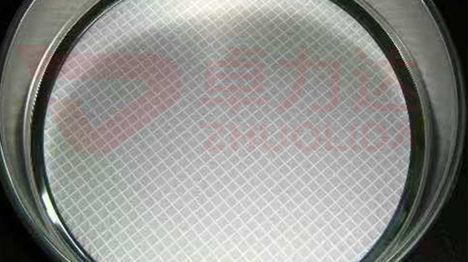
Electroformed micro-hole mesh aperture tolerance control governs the size spread across a whole batch of openings, not whether a sampled handful passes. The tolerance band is only ±3 μm, and developer scum, current density, release stress and anneal spring-back each slip a micron or two into it; each stage alone looks inside the window, stacked together they cross the line. Worse, the spread is not even: centre and edge often sit at opposite ends of the band, and nine points in the middle will never show it. So this process puts its weight on how re-measurement is done — scan the full sheet zone by zone, judge against the datum frame, turn 'the lot is consistent' into checkable data instead of one line saying sampling passed.
The classic floor failure is incomplete development. A thin resist film left at the hole bottom makes nickel grow from a narrowed mouth; the front-end vision system sees a tidy hole, then release re-measurement puts the whole lot at the lower edge of the band and dozens of sheets go back together. The second is edge effect: current density runs higher at the panel edge, nickel builds faster and the aperture draws inward, so centre and edge can differ by over 3 μm, and a sampling plan covering only the centre leaves tens of thousands of corner holes unchecked. Too few sampling points is another — the customer finds an out-of-tolerance corner after shipment and the inspection card turns out never to have listed the edge zone. Anneal temperature left unlogged lets stress release nudge an already-passed aperture away again. Any one of these is minor; stacked into a ±3 μm band they are fatal, and electroformed micro-hole mesh aperture tolerance control exists precisely for that stacking.
Parameter Window
• Micro-hole mesh aperture tolerance ±3 μm, judged zone by zone over the full sheet, never a single spot standing in for the whole part.
• Minimum aperture ≥25 μm, pitch ≥120 μm, web ≥50 μm; a narrowed mouth hits the smallest holes hardest in relative terms.
• Position accuracy ±7 μm and aperture accuracy ±3 μm logged separately, not folded into one pass-or-fail verdict.
• Stencil thickness 15–200 μm; thick sheets grow sidewalls longer, so aperture shrinkage is harder to predict than on thin foils.
• Lamination LDI resolves 8 μm/8 μm with ±5 μm double-side alignment; exposure-side deviation carries straight into the aperture.
• Bath current density 1–4 A/dm²; the edge-to-centre thickness spread shows up directly as an aperture spread.
Manufacturing Process (8 Steps)
1. Artwork data — generate the master from the aperture drawing, write aperture and the ±3 μm band into the inspection card first.
2. Pre-treatment — clean and conductivise the substrate, passivate the mandrel face for low adhesion.
3. Lamination and LDI — imported LDI exposure at 8 μm/8 μm resolution, ±5 μm double-side alignment.
4. Development — check the hole base for scum sheet by sheet, no resist allowed at the aperture.
5. Deposition — staged 1–4 A/dm² control to suppress the thickness spread from edge effects.
6. Release and anneal — peel the whole sheet from a low-stress corner, low-temperature anneal sets the shape, log temperature per lot.
7. Zone re-measurement — automatic checker scans every aperture, vision system and flash measurement confirm edge and corners.
8. Judgement and delivery — read each zone against the ±3 μm band, trace out-of-tolerance sheets back to bath run and exposure lot.
Core Advantages
1. Full-sheet coverage — zone scanning replaces nine-point sampling, so corner and edge misses never reach the customer; that is the floor of electroformed micro-hole mesh aperture tolerance control.
2. Deviation is separable — re-measurement data at development, deposition and release localises an out-of-tolerance reading to a concrete step.
3. Dimensional consistency — centre and edge fall in the same band, so grading and printing behaviour stay close from lot to lot.
4. Tolerance stays clear — ±3 μm reaches the customer as clean space, not a margin already spent by upstream deviation.
5. Complete records — each sheet carries a zone aperture map and bath number, reviewable one by one if a dispute arises.
6. Less rework — problems are caught at post-release re-measurement instead of coming back after assembly.
Typical Applications
1. Precision screens for semiconductor material grading, where aperture spread sets how steep the grading curve is.
2. Wafer-level ball-placement masks with over a million openings, where aperture consistency is a precondition for solder volume consistency.
3. BGA and Mini LED printing stencils, where a narrowed mouth makes paste release run light across the sheet.
4. Nebuliser plates and micro-hole meshes with ±3 μm aperture tolerance, leaving almost no room for deviation.
5. Probe positioning templates, where aperture and position are capped together to hold probe clearance.
6. Large-format photovoltaic grids, where centre-to-edge spread grows with area and zone scanning matters most.
Design and Selection Notes
1. Write the zone plan into the inspection card first — centre, edge and four corners as separate zones, not just nine points.
2. Add a base-scum check after development; resist at the mouth is harder to find than a miscalculated aperture.
3. Hold current density in one segment of 1–4 A/dm²; changing segment means re-measuring the edge-to-centre aperture difference.
4. Set separate re-measurement points for thick and thin sheets, the 15–200 μm ends shrink differently.
5. The ±5 μm double-side figure belongs to exposure; post-release zone re-measurement is the delivery figure.
6. Log anneal temperature per lot and count dimensional spring-back inside the band, do not treat it as zero.
7. Fix the zone map, judgement rules and re-measurement equipment at sampling stage, then release to that card.
Put electroformed micro-hole mesh aperture tolerance control back on the whole line and it is closer to a judgement method than a tuning knob on any one step. Clean development gives 'no narrowed mouth', steady current gives 'centre and edge grow alike', zone re-measurement gives 'deviation has nowhere to hide'; only then is ±3 μm a number that can be delivered. What separates capable lines is rarely whether one sheet can be made inside tolerance, but whether a dozen sheets from one bath, and the next lot after it, still land on the same distribution. For orders specifying micro-hole mesh aperture re-measurement, write the zone map, judgement rules and anneal temperature into the process card at sampling stage, then scan full sheets to that card in production, far cheaper than sorting sheets afterwards or re-measuring after a customer return. That is where electroformed micro-hole mesh aperture tolerance control earns its keep: turning 'consistent' into visible zone data.
Contact:赖先生
Phone:+86 18938693450
Tel:0755-2708-8292
Email:yw9@zldsmt.com
Add:深圳市宝安区福永镇新和村福园一路华发工业园A3栋
 Zhuolida
