Welcome: Shenzhen Zhuolida Electronics Co.TD
Language:
 ∷

∷
∷
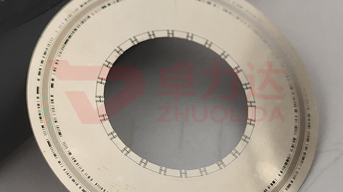
Take the same encoder disc: a 30 μm foil flexes, a 200 μm one is stiff, yet stiff is not automatically easier to mount. Encoder disc thickness grading control governs a chain of knock-on effects behind that seemingly simple number. The longer deposition runs, the more grain and internal stress accumulate, and after release the plane slowly bows; a thin foil carries less stress but cannot take the pull of release and tensioning without a wavy edge. Grading is not just cutting 30–200 μm into a few ranges to quote the customer. Each band gets its own current curve, anneal temperature and flatness acceptance line so that thickness, residual stress and installed air gap all balance inside one window. QC measures thickness with a single number; the line has to watch the stress difference at every point across the whole plane. A dozen microns of spread inside one band can split installed behaviour two ways, so band boundaries are not drawn by guess but read back from flatness re-test data.
Without grading, failures arrive in batches. One lot of 200 μm discs measured within thickness tolerance, yet a week after mounting the read head started dropping pulses; a vision system showed the centre sitting more than ten microns above the edge, because current density was pushed up late in deposition, internal stress was never fully relieved, and the disc sprang back slowly after release. A 40 μm lot was more direct: a flash scan found a wave around the rim, the disc would not sit flat on its mounting face, and the air gap wandered — the thin foil had been peeled without temporary support and kept a permanent set. Then there was a mixed lot, 50 μm and 150 μm in the same bath sharing one anneal curve: the thin parts were fine, the thick ones still held stress, flatness passed at dispatch and the parts bowed days later at the customer. With encoder disc thickness grading control missing, all of it piles up until after mounting. That thick-disc lot was remade later, with late-stage current pulled back to the low end and a separate anneal band, and only then did the plane hold — a full extra round of trial mounting.
Parameter Window
• Disc thickness 30–200 μm, split into 30–50, 50–100 and 100–200 μm bands with separate process cards
• Aperture accuracy ±3 μm and aperture wall roughness ≤0.01 μm, re-measured with one gauge across all bands
• Nickel alloy hardness 450–550 Hv; extra brightener lifts hardness but drags internal stress up with it
• Bath current density 1–4 A/dm²; thick discs favour the low end with zoned feed to hold thickness spread
• LDI resolution 8 μm/8 μm and ±5 μm double-side alignment, several discs on substrates up to 610×660 mm
• Track width 50 μm±0.5 μm; a bowed plane shifts the whole revolution's line-width reading with it
Manufacturing Process (8 Steps)
1. Set the band by installed air gap — establish read-head clearance and mounting face first, then choose a thickness in 30–200 μm, not the other way round.
2. Mandrel pre-treatment — clean and conductively coat the master, with adhesion tuned for clean whole-sheet release without mid-run lifting.
3. Lamination and LDI — imported LDI exposure at 8 μm/8 μm, ±5 μm double-side alignment, pattern laid out on 610×660 mm.
4. Development and strike — develop clean and lay a low-current base so thin bands start from an even plane without a stress gradient from the outset.
5. Graded deposition — thick bands run at the low end of 1–4 A/dm² with zoned feed, thin bands are controlled by total time, both watched for thickness spread as they grow.
6. Supported release — thin bands are peeled on a temporary carrier, thick bands start from a low-stress corner, so the plane is not pulled into waves.
7. Low-temperature anneal — temperature and soak time set by thickness band, releasing residual stress so it does not spring back after mounting.
8. Flatness re-test — vision and flash measurement for whole-plane flatness and thickness distribution, judged band by band before shipping.
Core Advantages
1. Plane stays put — thickness, stress and anneal matched by band, so the air gap holds and the read head does not drop pulses.
2. Thin bands do not warp — 30–50 μm parts peel on a carrier, and wavy edges are stopped inside the process.
3. Thick bands do not bow — 100–200 μm runs at low current for longer, accumulating less stress and less spring-back.
4. Mixed lines stay clean — different bands in one bath follow their own curves, so flatness no longer swings between lots.
5. Mandrel survives — release conditions set by thickness, so fine ribs on the master are less likely to be rounded off by a heavy disc, and encoder disc thickness grading control protects tool life too.
6. Traceable — current curve, anneal temperature and flatness map are logged per band, so anomalies trace back to the run.
Typical Applications
1. Incremental and absolute encoder discs, where an air gap of a few to tens of microns makes flatness a direct signal-quality factor.
2. Servo motor and robot joint feedback discs, where long vibration makes thick-disc stress relief bow the plane over time.
3. Elevator traction and hoist speed discs, where wide temperature swings and long duty mean the thickness band must be chosen with thermal deformation.
4. Precision rotary table and optical goniometer index discs, where whole-plane flatness affects division error more than a single-point thickness.
5. Miniature encoder thin discs, where the 30–50 μm band must be both light and flat, making supported release mandatory.
6. High-resolution multi-track thick discs, where bands above 100 μm rely on low-stress deposition to hold line-width consistency around a revolution.
Design and Selection Notes
1. Fix the air gap before the thickness. Write read-head clearance and mounting-face flatness into the agreement, not a lone thickness number.
2. Do not mix bands in one order. A 30 μm and a 150 μm part sharing one anneal curve always leaves one of them with stress still inside.
3. Do not rush thick discs. Hold current at the low end of 1–4 A/dm²; slower deposition means less plane spring-back later.
4. Thin discs must be released on support. Skip that carrier and even well-controlled stress is wasted.
5. Measure flatness across the whole plane. Centre and four corners alone miss a bowed middle that only shows up after mounting.
6. Set anneal temperature by band. Over-anneal softens thin parts, under-anneal leaves stress in thick ones; the numbers cannot be copied across.
7. Ship with a flatness map. A vision system gives geometry, a flash system gives distribution; only together do they match installed behaviour.
Laid out, encoder disc thickness grading control is not simply drawing a few intervals on a thickness scale; it governs how stress accumulates, how it is released, and whether it moves after mounting across 30–200 μm. Low-current deposition accumulates less stress, graded anneal releases it cleanly, and supported release keeps thin foils from being pulled out of shape. Miss any one and ±3 μm aperture accuracy means little once the plane bows. What separates capable lines is rarely how precisely a single thickness is measured, but whether a dozen parts in one band, re-checked days later, still agree on flatness. For orders that specify electroformed disc thickness uniformity, fix the air-gap condition, band boundaries and each band's anneal curve into the process card at sampling stage, then run to that card — far easier than screening flatness after mounting. The value of encoder disc thickness grading control is turning a one-dimensional thickness number into a delivery condition with a stress budget attached.
Contact:赖先生
Phone:+86 18938693450
Tel:0755-2708-8292
Email:yw9@zldsmt.com
Add:深圳市宝安区福永镇新和村福园一路华发工业园A3栋
 Zhuolida
