Welcome: Shenzhen Zhuolida Electronics Co.TD
Language:
 ∷

∷
∷
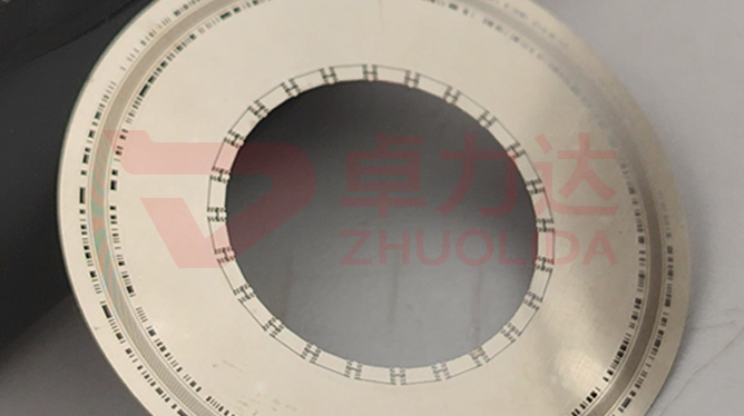
An incremental optical encoder disc carries several hundred to more than two thousand alternating bright and dark tracks around its rim, each rib and slot 50 μm wide with tolerance held to ±0.5 μm. Encoder disc track replication accuracy is not about how accurate the finished part measures, but about how much of the original line on the mandrel survives coating, exposure, development and electroforming into the nickel layer. Electroforming does not cut vertical sidewalls the way lithography can; nickel grows bit by bit along the resist pattern, so a slight taper in the resist wall, a film of residue after development, or a few microns of extra edge growth all shift the track duty cycle, and the square wave from the read head drifts with it. Controlling replication accuracy means treating the mandrel's geometric fidelity as a budget spent across every step, with each stage's loss and recovery accounted for.
Line failures almost always come from the replication stage. One batch used a freshly made glass mandrel with crisp track edges, yet the nickel discs measured slots about 1.5 μm wider than the mandrel under a vision system; the cause was insufficient post-development bake, so the resist wall swelled slightly in the bath and nickel grew along the swollen sidewall. Another batch was subtler: every single rib passed a flash measurement scan, but once installed the encoder output duty cycle wandered. It turned out that on a 610×660 mm panel the current density differed between edge and centre, so deposition rate varied and tracks around one revolution took on different amounts of growth. There was also the case of a mandrel reused too many times, where release pulled a few fine ribs into rounded corners, and every nickel disc afterwards missed the same corner at the same spot — encoder disc track replication accuracy was permanently degraded by damage to the tool. Incoming inspection catches some of these, but waveform trouble often only shows up once the disc is mounted on a motor.
Parameter Window
• Track rib and slot width 50 μm±0.5 μm, re-measured track by track; duty-cycle error starts here
• Disc thickness 30–200 μm; thicker discs spend longer in lateral growth, so edge gain is harder to hold
• LDI resolution 8 μm/8 μm and ±5 μm double-side alignment; the resist pattern is where fidelity begins
• Maximum substrate 610×660 mm; current distribution across the panel sets consistency around one revolution
• Bath current density 1–4 A/dm²; at the high end edge effects show up and fine ribs tend to fatten
• Nickel alloy hardness 450–550 Hv; hardness bought with additives also changes sidewall growth shape
Manufacturing Process (8 Steps)
1. Mandrel preparation — produce the track pattern on a glass or silicon master, record measured rib and slot values as the replication baseline, scrap any scratched plate.
2. Pre-treatment and conductive coating — clean the mandrel and sputter a conductive layer, with adhesion tuned to avoid both lifting and difficult release.
3. Lamination and LDI — imported LDI exposure at 8 μm/8 μm resolution, ±5 μm double-side alignment, several discs laid out on a 610×660 mm panel.
4. Development and bake — control development time and post-bake temperature to keep resist walls straight and residue-free, preventing swelling in the bath.
5. Low-current strike — lay a thin nickel layer along the resist pattern at low current first, locking the mandrel line width before building upward.
6. Staged electroforming — feed 1–4 A/dm² by zone, shield the edges, supplement the centre, and hold down thickness spread and lateral growth.
7. Release and anneal — peel the whole disc from a low-stress corner, then low-temperature anneal to remove stress so tracks do not spring back.
8. Re-measure and grade — vision and flash measurement for rib and slot width track by track, graded by duty cycle and deviation from 50 μm±0.5 μm.
Core Advantages
1. Mandrel shape survives — strike-locked line width plus zoned feed keeps rib and slot growth from resist to nickel at sub-micron level.
2. Stable waveform — duty cycle stays consistent around a revolution, so the read head square wave does not widen and narrow.
3. Consistent across a panel — several discs on 610×660 mm share current conditions, narrowing lot-to-lot spread.
4. Mandrel life under control — reuse count and per-plate replication error are logged, and the plate is swapped before fine ribs round off and drag encoder disc track replication accuracy down with it.
5. Thin and thick discs both work — the 30–200 μm range gets its own deposition curve rather than one shared recipe.
6. Traceable — mandrel ID, development batch and track-by-track readings are logged per part, so anomalies trace back to the plate.
Typical Applications
1. Incremental optical encoder discs, where the bright-dark duty cycle of several hundred to two thousand tracks sets resolution directly.
2. Absolute encoder multi-track discs, where inner and outer rings differ in line width and replication gain must be corrected ring by ring.
3. Servo motor and robot joint feedback discs, where vibration makes rounded track edges a source of read jitter.
4. Elevator and hoist speed discs, where long service demands that ribs and slots do not drift through stress spring-back.
5. Precision rotary tables and optical goniometer index discs, more sensitive to consistency around one revolution than to a single line.
6. Miniature encoder discs, where 50 μm ribs and slots are already near the limit and replication margin is tighter than on large discs.
Design and Selection Notes
1. Ask for the mandrel measurement report first. If the master's ribs and slots were never measured, a clean finished-part reading has nothing to compare against.
2. On high-track-count discs do not read single line width alone; duty-cycle variation around the whole revolution is the installed figure.
3. Thin discs of 30–50 μm have short lateral growth and small gain, but release distorts them easily, so support the peel.
4. The ±5 μm double-side figure belongs to exposure; track-by-track re-measurement after release is the delivery figure.
5. Do not sit at the current ceiling. Holding 4 A/dm² for long runs fattens edge tracks before the centre catches up.
6. Set a reuse limit for the mandrel. Once fine ribs show a rounded corner or resist residue, every later part carries the same defect.
7. Put waveform testing into acceptance. A vision system measures geometry; duty-cycle trouble only appears with a read head fitted.
Seen on its own, encoder disc track replication accuracy is less a single-step figure than a reconciliation of the mandrel, lithography and electroforming. The master supplies the original line at 50 μm±0.5 μm, development supplies a straight resist wall, and zoned feed keeps nickel from growing an extra sliver at the edge. Let any one slip and the finished ribs and slots no longer match the plate. What is hard on a real line is not making one disc pass, but holding the same replication coefficient across a dozen discs on a 610×660 mm panel and across several lots. For orders that specify electroformed disc mandrel fidelity, fix the master ID, post-bake condition and panel current distribution into the process card at sampling stage, and file the track-by-track data against the plate revision — cheaper than screening out bad waveform parts after mounting. That is where encoder disc track replication accuracy lands: turning an invisible fidelity into a measurable, traceable parameter.
Contact:赖先生
Phone:+86 18938693450
Tel:0755-2708-8292
Email:yw9@zldsmt.com
Add:深圳市宝安区福永镇新和村福园一路华发工业园A3栋
 Zhuolida
